12
The figure is for reference only. The actual interface may be different and shall
prevail.
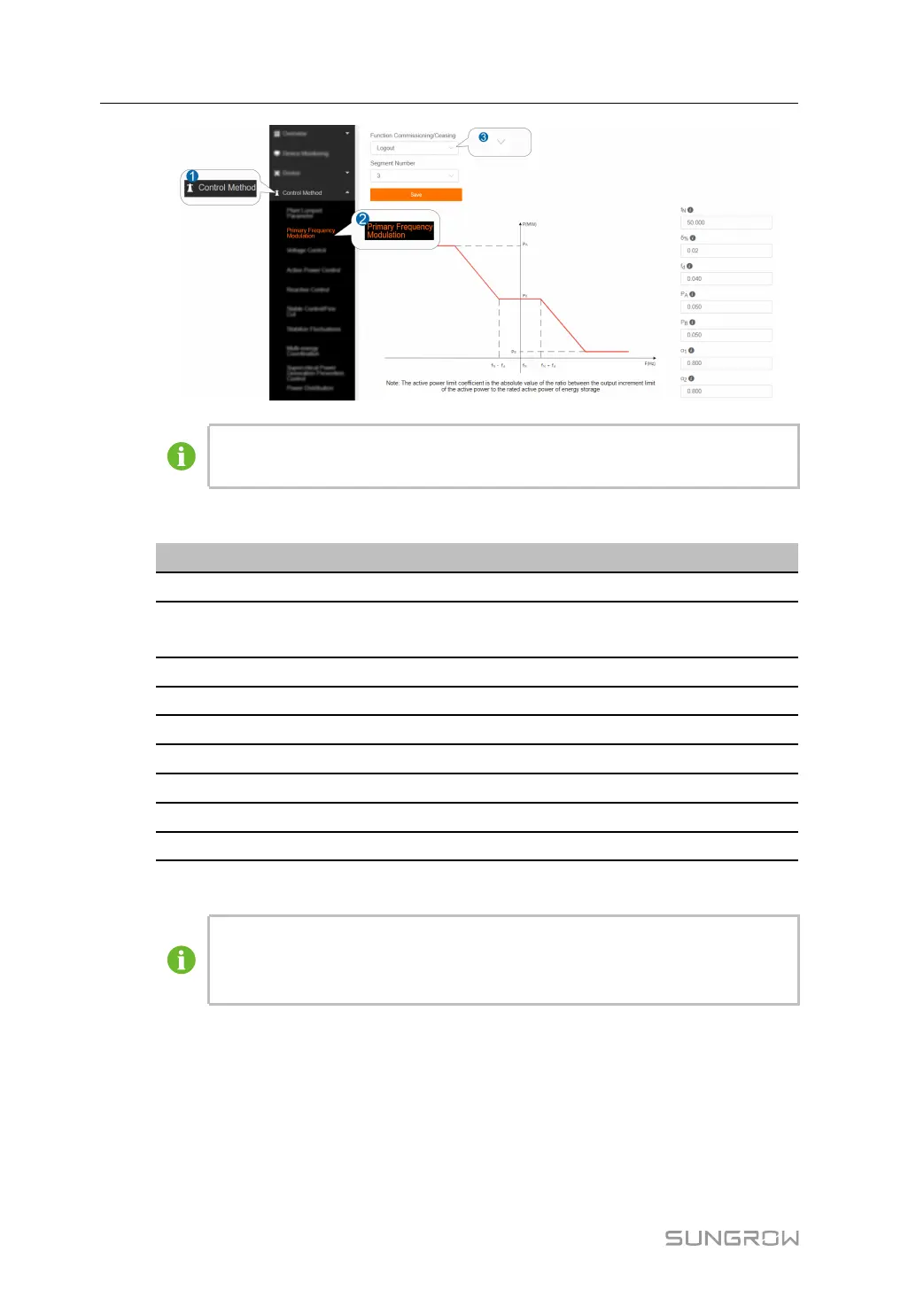
step 3 Set the right frequency modulation parameters, which are described as shown below.
PPaarraammeetteerrss
DDeessccrriippttiioonnss
f
N
Rated frequency of grid-connection point
δ%
Frequency regulation coefficient (δ%=-△f(%)/△P
(%))
f
d
Frequency modulation dead zone
P
A
Maximum output active power
P
B
Maximum active power PB absorbed
α
1
Lower limit of active power limit coefficient
α
2
Upper limit of active power limit coefficient
δ
2
% *
Frequency modulation II regulation coefficient
f
d2
*
Frequency modulation II dead zone
* indicates the parameter to be set when the segment number = 5.
The active power limit coefficient is the absolute value of the ratio between the
output increment limit of the active power to the rated active power of energy
storage.
-- -- EEnndd
6 Control Method User Manual