13
6.3 Voltage Control
6.3.1 Dynamic Reactive Voltage Regulation
This function can monitor the real-time voltage at the grid-connected point, and regulate
reactive power dynamically to stabilize the voltage if it changes beyond the voltage
regulation dead zone.
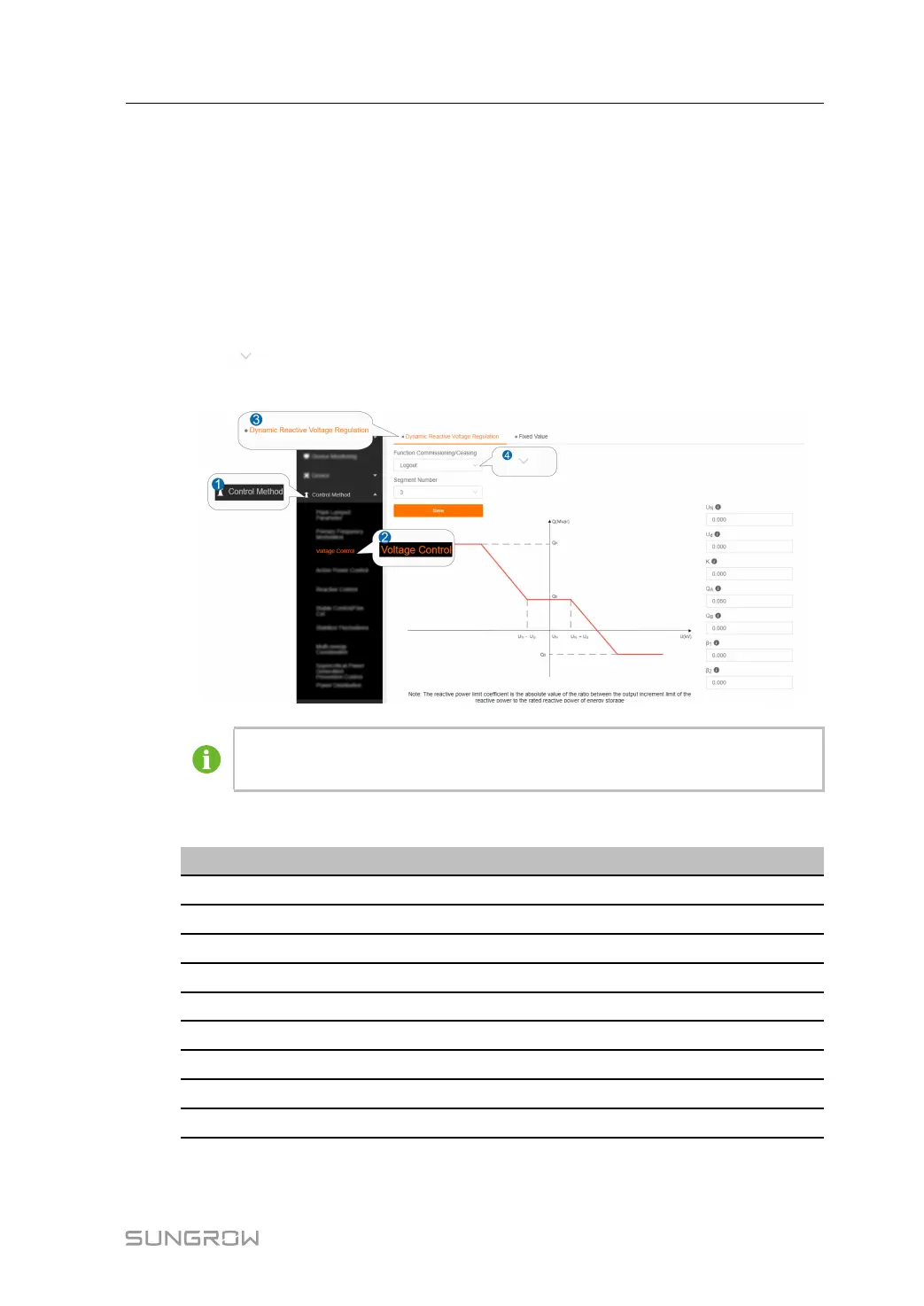
step 1 Click CCoonnttrrooll MMeetthhoodd→→VVoollttaaggee CCoonnttrrooll→→DDyynnaammiicc RReeaaccttiivvee VVoollttaaggee RReegguullaattiioonn to
enter the corresponding interface.
step 2 Click
to set the status of FFuunnccttiioonn CCoommmmiissssiioonniinngg//CCeeaassiinngg and SSeeggmmeenntt
NNuummbbeerr, and click SSaavvee.
The figure is for reference only. The actual interface may be different and shall
prevail.
step 3 Set the right voltage modulation parameters, which are described as shown below.
PPaarraammeetteerrss
DDeessccrriippttiioonnss
U
N
PV rated line voltage
U
d
Voltage regulation dead zone
K
Voltage regulation coefficient (K=-△Q(%)/△U(%))
Q
A
Maximum output reactive power
Q
B
Maximum reactive power absorbed
β
1
Lower limit of reactive power limit coefficient
β
2
Upper limit of reactive power limit coefficient
K
2
*
Voltage regulation II coefficient
U
d2
*
Voltage regulation II dead zone
* indicates the parameter to be set when the segment number = 5.
User Manual 6 Control Method



 To Next Page