17
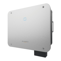
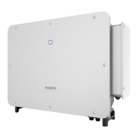
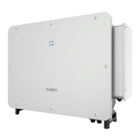
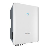
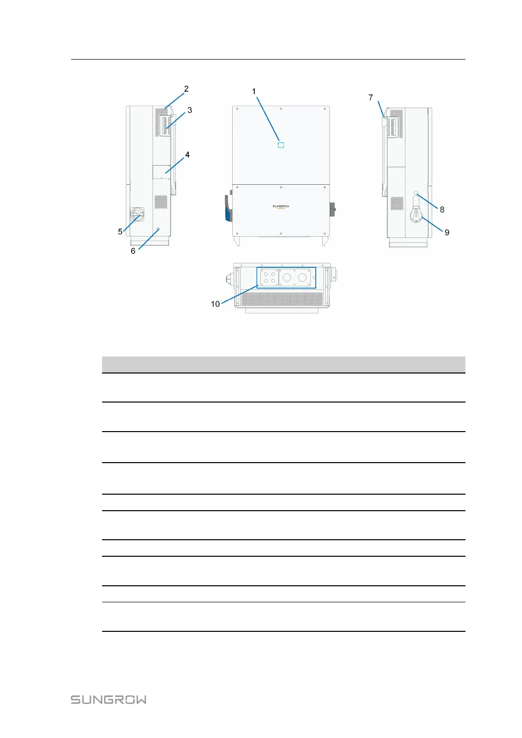
figure 2-12 Product Components Description
*Image shown here is for reference only. Actual product you receive may differ.
NO. Name
Description
1
LED indicator panel
HMI interface to indicate the present working state of
the device.
2 Air outlet
Controlled forced-air cooling method. Ensures proper
ventilation.
3 Handles
Handles are designed for transporting, installing and
disassembling the device.
4
Cover plate of the
fan
The fan is located on the back of the cover plate and
used for the forced cooling of the device.
5 AC switch
To disconnect the device from the AC output safely.
6
Second PE
Terminals
Second protective earth terminals as specified in EN
50178.
7
Hanger Hang the device on the bracket.
8
Emergency stop
button
Stop the device in emergency by pressing this button
down.
9 BAT. Switch
To disconnect the device from the battery safely.
10
Electrical
connection area
Includes DC terminal, AC terminal and communication
terminal.
LED Indicator Panel
As an HMI, the LED indicator panel on the device front panel indicates the present working
state of the device.
System Manual 2 Product Description