42
Grounding Cable
Use a grounding cables of 70mm
2
~ 95mm
2
to ensure a reliable connection between the
grounding points and the grounding points of the ESS. (The grounding point is covered with
protective tape before delivery. Remove the tape before wiring.)
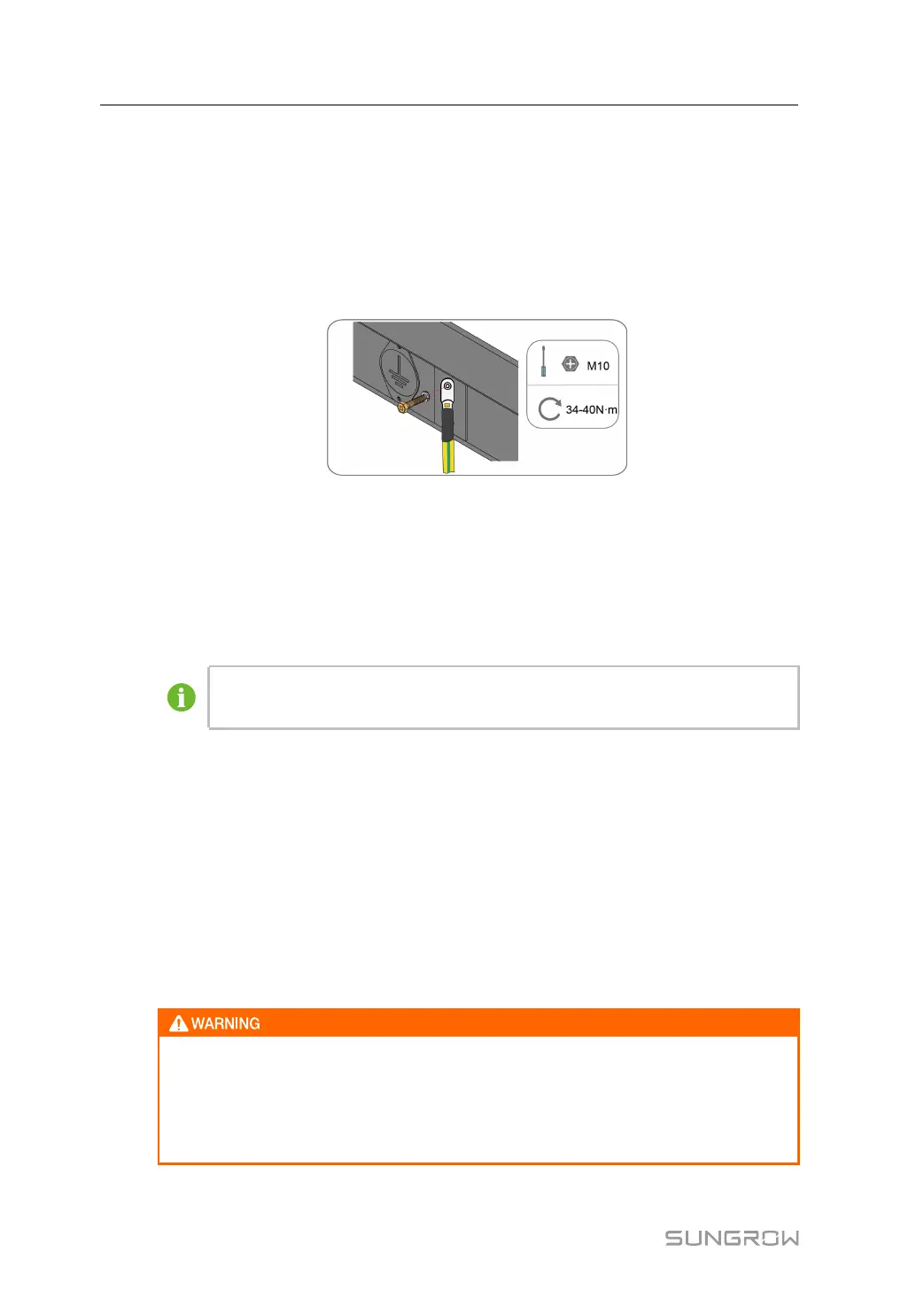
Crimp DT terminals, refer to "5.3.3 Preparing Cables" for detailed steps. Use grounding
cables to ensure a reliable connection between the grounding points and the grounding
points of the ESS. When finished, tighten them with M10 bolts.
figure 5-10 Grounding cable diagram
*The figure is for reference only and the actual product shall prevail.
Please perform the external grounding connection according to the actual on-site condition
and the instructions of the plant personnel.
The grounding resistance shall be measured after the ground connection is finished, and the
resistance value shall be no more than 4Ω.
The specific grounding resistance shall comply with relevant national/local
standards and regulations.
5.5 DC Cable Connection
5.5.1 Safety Precautions
Check the following items before cable connections.
• Measure the open circuit voltage on the battery side to ensure that the open circuit
voltage does not exceed the maximum DC voltage of the downstream PCS.
• Mark the negative and positive polarity of the cable.
• Check whether there is a ground fault on the battery side.
• The open circuit voltage on the battery side cannot exceed the maximum DC
input voltage of the downstream PCS. Excessive open circuit voltage on the
battery side may cause damage to the downstream PCS.
• When a ground fault is found on the battery side, the DC input terminal of the
downstream PCS must be connected after the fault has been cleared.
5 Electrical Connection System Manual