48
step 1 Confirm that the circuit breakers of the front and rear equipment are all off.
step 2 Pass the cables out of the PCS cabinet and into the BESS cabinet through the inlet and
outlet holes.
step 3 Make sure that the AC cables are connected in the correct order.
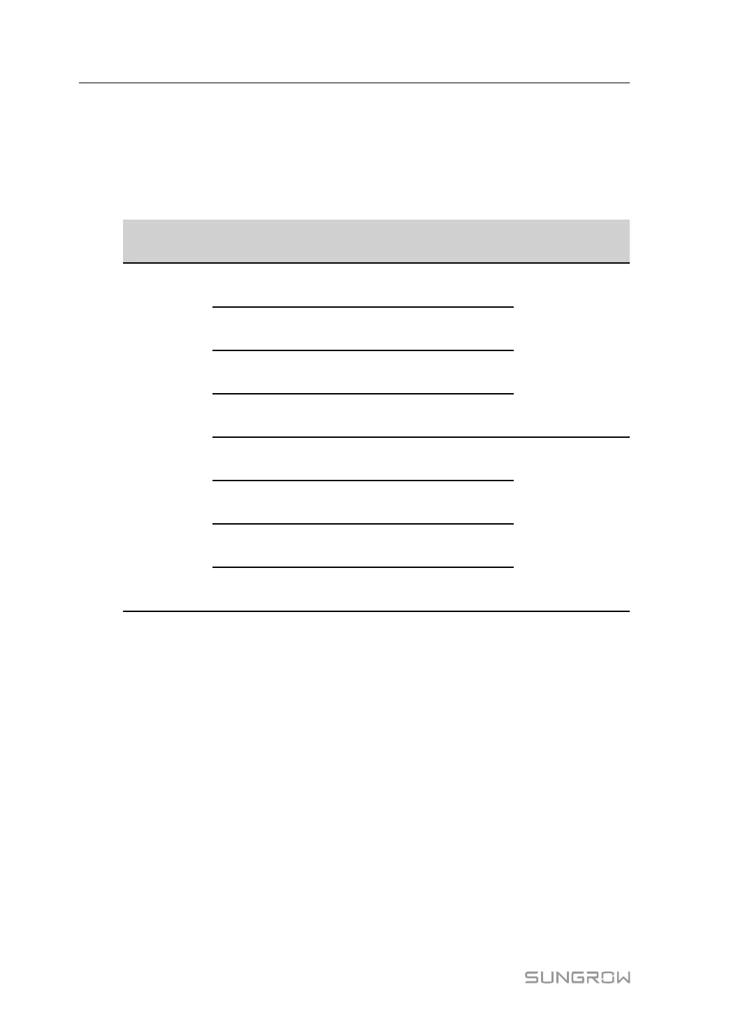
table 5-3 Port description
Cabinet Mark
Description
*Recommended
specification
PCS cabinet
XK4–1
Connect to AUX POWER terminal
L1 phase of 1# BESS
4 mm
2
XK4–2
Connect to AUX POWER terminal
L2 phase of 1# BESS
XK4–3
Connect to AUX POWER terminal
L3 phase of 1# BESS
XK4–4
Connect to AUX POWER terminal N
phase of 1# BESS
XK5–1
**Connect to AUX POWER terminal
L1 phase of 2# BESS
4 mm
2
XK5–2
**Connect to AUX POWER terminal
L2 phase of 2# BESS
XK5–3
**Connect to AUX POWER terminal
L3 phase of 2# BESS
XK5–4
**Connect to AUX POWER terminal
N phase of 2# BESS
*The noted cable specifications are recommended values. It can be adjusted according to
actual needs.
**Indicates that the 2# BESS cabinet is optional.
step 4 Wiring according to the port identification and definition. Tighten with a screwdriver with a
torque of 0.7±0.1 N·m.
- - End
5.9 24Vdc Power Supply Connection
The power cable drawn from the BESS cabinet is connected to the PCS cabinet to supply
24Vdc power to the LC and switches in the PCS cabinet. The output port is located in the
CONN4 terminal block of the BESS cabinet, and the input port is located in the XK6 terminal
block of the PCS cabinet.
step 1 Confirm that the circuit breakers of the front and rear equipment are all off.
5 Electrical Connection System Manual