35
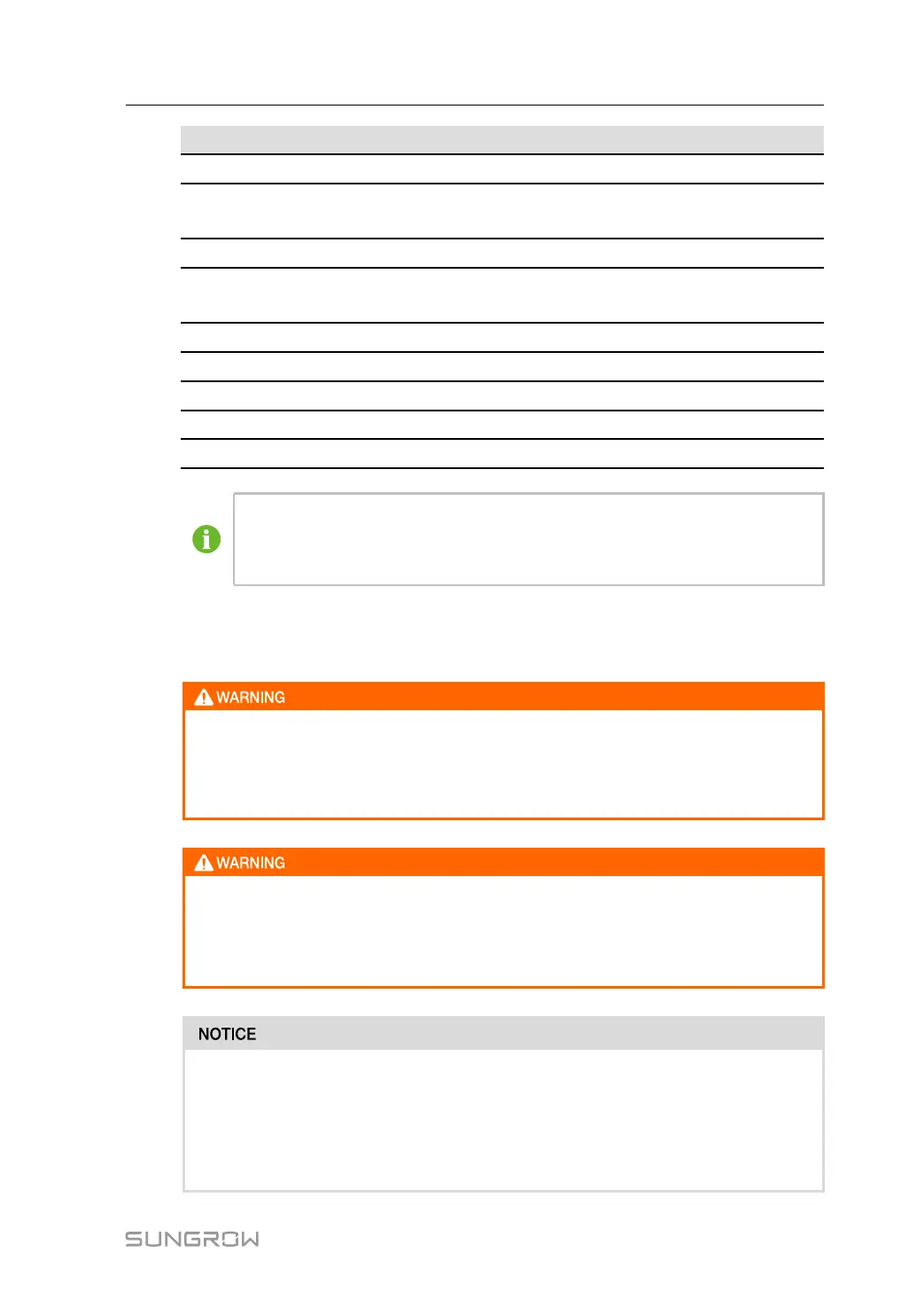
No. Item
Recommended specification
D
Battery DC side to PCS DC side
240 mm
2
E
Auxiliary power supply interface of
battery cabinet
4 mm
2
F
DC24V power supply interface
2.5 mm
2
G
BESS/PCS cabinet grounding
70mm
2
~ 95mm
2
grounding cable
or grounding flat steel
H
EMS power supply interface
2.5 mm
2
I
EMS cabinet grounding 16mm
2
grounding cable
COM1
1# BESS ethernet wiring
CAT6A network cable
COM2
2# BESS ethernet wiring(Optional)
CAT6A network cable
COM3
EMS ethernet wiring
CAT6A network cable
*Default B and C shorted, system auxiliary internal power supply.
If external power supply mode is used, the wiring between B and C needs to be
removed and port C connected to an external power supply.
The above cables are not included in the scope of supply and need to be prepared
separately.
• All electrical connections must be carried out in strict accordance with the
wiring schematic diagram.
• All electrical connections must be made when the equipment is completely de-
energized.
Only qualified electrical engineers can carry out work related to electrical
connections. Please comply with the requirements given in “2 Safety Instructions”
in this manual. The company does not assume any responsibility for casualties or
property losses caused by ignoring these safety instructions.
• The installation design of the BESS and PCS must comply with the relevant
standards or regulations of the country/region where the project is located.
• If the installation is not carried out in accordance with the installation design
requirements given in this manual, which causes the BESS and PCS or system
failure, it will not be covered by the warranty.
System Manual 5 Electrical Connection