49
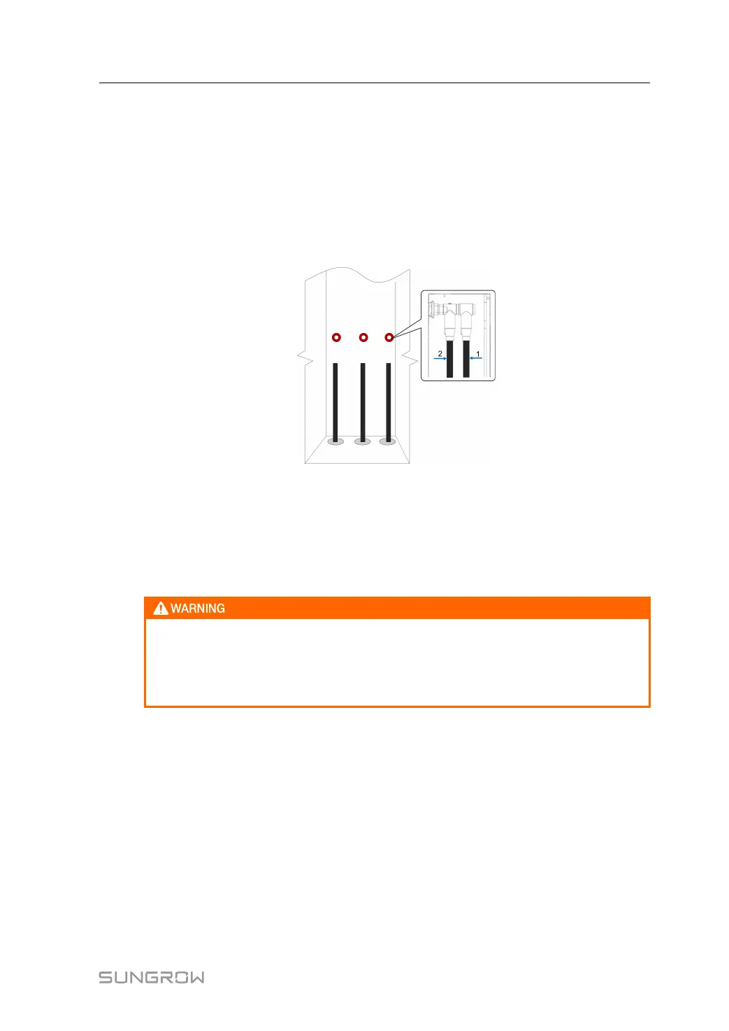
step 2 Prepare the terminals and install them tightly, where reference can be made to the cable
connector installation manual.
The wiring terminal can be connected with either copper cable or aluminium cable.
• In case of copper cable, use copper wiring terminals.
• In case of aluminium cable, use copper-to-aluminium adapter terminals.
The HV wiring terminal can be connected to a maximum of two cables, corresponding to the
right-side terminal (Figure 1) and left-side terminal (Figure 2). Select the terminal as needed.
- - End
Further Operations
Seal the bottom cable entries with fire-proof mud, clear sundries inside the cabinet, and re-
assemble the sealing plate of the cabinet.
Should there be any unused wiring terminals, block them with insulating caps.
Upon the completion of electrical connection, before the PCS is connected to the
grid, it is required to enter the HV room, and inspect the bushings of the MV trans-
former and cables connecting HV room transformer for anything abnormal such as
loose connection and damages.
6.9 Communication Connection
There are several communication ports reserved for external connection: 2 internet commu-
nication ports; 6 RS485 communication ports; 1 Can communication port for BMS; and dry
contact input port. The following figure shows the maintenance communication ports:
System Manual 6 Electrical Connection
 Loading...