83
fault state will not be removed until the user presses the start/stop button or the emergency
stop button manually.
10.1.3 Mode Switching
When the PCS is powered up and enters initial stop state, the control system will perform
self-test to check the control and sensor systems. When the DSP normally starts, the PCS
enters key stop state. In this state, the PCS blocks IGBT pulse and the AC and DC switches
are open.
In the standby state, the PCS blocks IGBT pulse, but closes AC and DC switches, and the
PCS is in hot standby state.
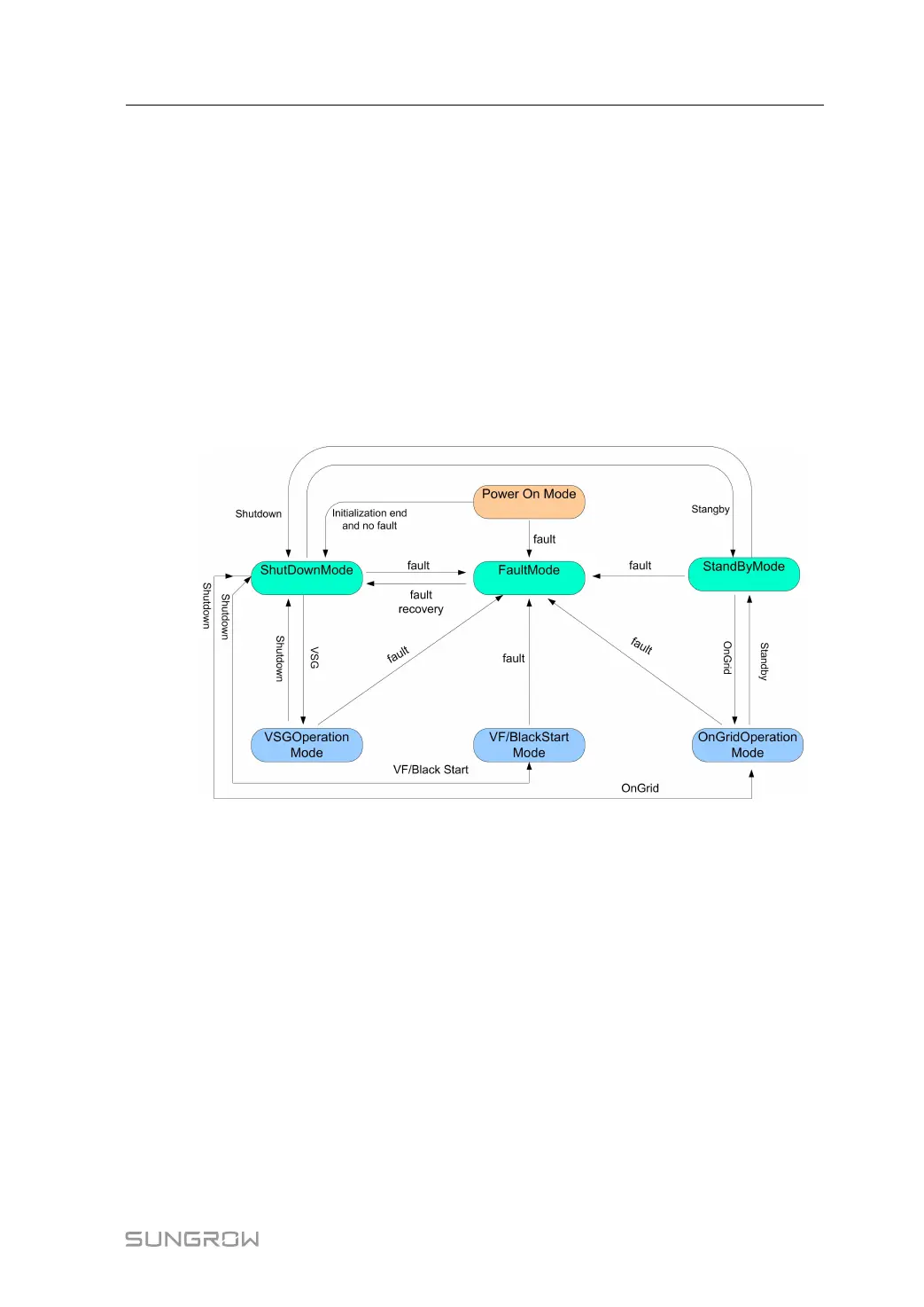
The PCS can switch among different modes, and switch conditions are shown in "figure 10-
5 Working mode switching diagram".
figure 10-5 Working mode switching diagram
10.1.4 Working Mode
On-grid Mode
In the on-grid mode, the PCS can implement the charging and discharging functions.
On-grid constant power (AC), on-grid constant power (DC), on-grid constant voltage, and
on-grid constant current;
All the on-grid modes are available in the charging and discharging state.
System Manual 10 PCS Functions
 Loading...