81
Parameter
Desciptions
Default
Range
Deadzone Deadzone voltage range (%) 0% 0%~5%
Minimum reac-
tive power ratio
Inductive Q/Sn value of point P4 in the
Q(U) mode curve
25% 0%~50%
Maximum reac-
tive power ratio
Capacitive Q/Sn value of point P1 in
the Q(U) mode curve
25% 0%~50%
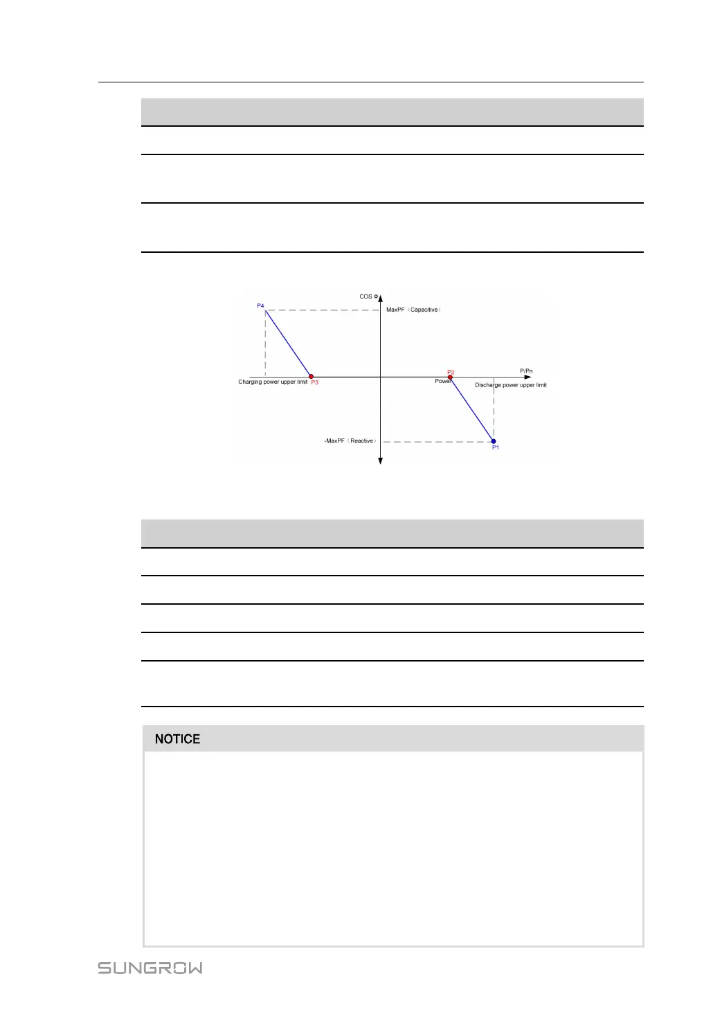
Q(P) Mode
figure 10-4 Q(P) curve
table 10-4 Q(P) Mode Parameters Descriptions
Parameter
Desciptions
Default
Range
Q(P)Curve P1 Output power (%) at P1 on Q(P) curve 100% 50%~100%
Q(P)Curve P2 Output power (%) at P2 on Q(P) curve 50% 0%~50%
Q(P)Curve P3 Output power (%) at P3 on Q(P) curve -50% -100%~50%
Q(P)Curve P4 Output power (%) at P4 on Q(P) curve -100% -100%~50%
MaxPF Power factor at P1 and P4 on Q(P)
curve
0.9 0.900~1
• When multiple machines are connected in parallel, enable the "Parallel Control"
under "System Parameters" before executing the off-grid mode.
• After off-grid, before executing grid-connected mode again, disable "Parallel
Control" under "System Parameters".
• When multiple units are connected in parallel with AC and DC, before executing
the off-grid mode, set the "Direct Parallel Mode" under "Operating Parameters"
to DC Parallel, and "Parallel Control" in "System Parameters" to enable.
• When multiple machines are connected in parallel, enable "Parallel Control"
under “System Parameters” before executing the VSG mode.
System Manual 10 PCS Functions
 Loading...