EasyManua.ls Logo

Suntex EC-4110 User Manual

Suntex EC-4110
45 pages
To Next Page IconTo Next Page
Page #1 background imageLoading...
Page #1 background image
1
EC-4110
ʳ
Intelligent
ʳ ʳ
Conductivity
Transmitter
Operation
Manual
Question and Answer IconNeed help?

Do you have a question about the Suntex EC-4110 and is the answer not in the manual?

Suntex EC-4110 Specifications

General IconGeneral
BrandSuntex
ModelEC-4110
CategoryTransmitter
LanguageEnglish

Summary

Precautions for installation

1. Specifications

2. Assembly and installation

2.1 Transmitter installation

Procedure for installing the transmitter using panel mounting.

2.2 Illustration of panel mounting

Diagrams showing panel mounting dimensions and hole spacing.

2.3 Illustration of Wall mounting and pipe mounting

3. Overview of Conductivity transmitter EC-4110

3.1 Illustration of rear panel

Diagram of the rear panel showing terminal layout and labels.

3.2 Illustration of terminal function

Block diagram illustrating terminal functions and connections.

3.3 Description of terminal function

3.4 Wiring of cable

3.5 Circuit of cable

3.6 Illustration of electrical connection

4. Configuration

4.1 Illustration of front panel

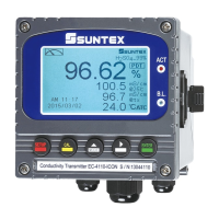
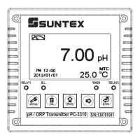
Diagram of the front panel showing controls and display indicators.

4.2 Keypad

Explanation of the function of each button on the keypad.

4.3 LED indicators

Description of ACT and B.L. indicator LEDs and their functions.

4.4 Display

5. Operation

5.1 Measurement mode

How to operate the transmitter in measurement mode after installation.

5.2 Set-up menu

Instructions for entering and navigating the set-up menu.

5.3 Calibration menu

Instructions for entering and navigating the calibration menu.

5.4 Shortcuts

Keyboard shortcuts for adjusting temperature compensation.

5.5 Reset

Procedures for performing master and calibration resets.

6. Settings

6.1 Entry of set-up menu

6.2 Security code of settings

6.3 Mode

6.4 Temperature

6.5 Compensation

6.6 Relay 1

6.7 Relay 2

6.8 Clean

6.9 Analog output 1 (Cond/Res)

6.10 Analog output 2 (Temperature)

6.11 Date/Time(Clock)

6.12 Sample average of measurements (Digital Filter)

6.13 Backlight settings

6.14 Contrast settings

6.15 Power frequency (Freq.)

6.16 Return

7. Calibration

7.1 Entry of calibration menu

7.2 Return

7.3 Security password of calibration (Code)

7.4 Cell constant calibration (CELL Const.)

7.4.1 Resistivity (Res)

Procedure for setting the cell constant for resistivity measurements.

7.4.2 Conductivity (Cond)

7.5 Standard solution calibration (Std. Sol.)

8. Error messages (Error code)

9. Installation of cells

9.1 Appearance of cells

Diagrams showing the physical appearance of conductivity cells.

9.2 Correct installation

Guidelines for correctly installing conductivity cells in applications.

9.3 Incorrect installation

Related product manuals