BIOS
FLASH
P2-DIMMH1
P2-DIMMG2
USB0/1
(3.0)
P2-DIMMH2
P2-DIMMF1
P2-DIMMF2
P2-DIMME2
P2-DIMME1
SIOM: CPU1 PCI-E 3.0 X16
P1-DIMMD1
P1-DIMMD2
P1-DIMMC1
P1-DIMMC2
CPU2 SLOT2
PCI-E 3.0 X16
C612
P2-DIMMG1
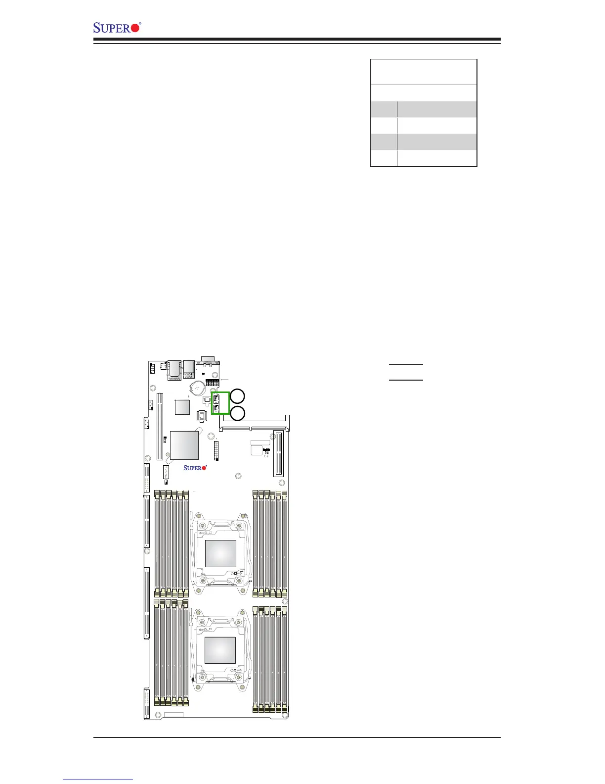
Fan Headers
This motherboard has two system fan
headers (FAN3, FAN4) on the mother-
board All these 4-pin fans headers are
backward compatible with the traditional
3-pin fans. However, fan speed control
is available for 4-pin fans only. The fan
speeds are controlled by Thermal Man-
agement via IPMI 2.0 interface. See the
table below for pin denitions.
Fan Header
Pin Denitions
Pin# Denition
1 Ground
2 +12V
3 Tachometer
4 PWR Modulation