BIOS
FLASH
P2-DIMMH1
P2-DIMMG2
USB0/1
(3.0)
P2-DIMMH2
P2-DIMMF1
P2-DIMMF2
P2-DIMME2
P2-DIMME1
SIOM: CPU1 PCI-E 3.0 X16
P1-DIMMD1
P1-DIMMD2
P1-DIMMC1
P1-DIMMC2
CPU2 SLOT2
PCI-E 3.0 X16
C612
P2-DIMMG1
2-9 Onboard LED Indicators
1. IPMI LAN LED
2. BMC Heartbeat LED
Dedicated IPMI LAN LED
An IPMI_LAN port, supported by the
ASpeed AST 2400 Baseboard Manage-
ment Controller (BMC), is located on the
back panel. This LAN port has two LED
indicators. The amber LED on the right
indicates activity, while the link LED on
the left indicates the speed of the con-
nection. See the tables on the right for
more information.
Link LED Activity LED
IPMI LAN
IPMI LAN Link LED (Left) &
Activity LED (Right)
Color/State Denition
Link (Left) Green 100 Mbps
Amber 1 Gbps
Activity (Right) Amber: Blinking Active
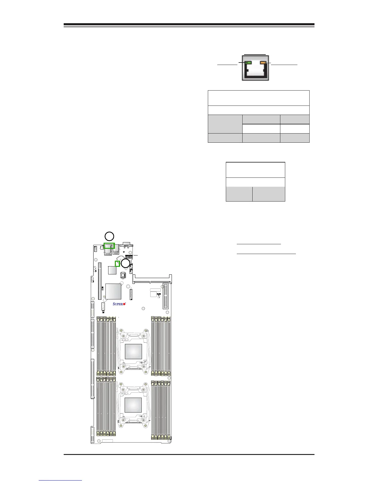
BMC Heartbeat LED
Status
Color/State Denition
Green:
Blinking
BMC: Normal
BMC Heartbeat LED
A BMC Heartbeat LED is located at
BMC_HB_LED1 on the motherboard.
When this LED is blinking, BMC func-
tions normally. See the table on the right
for more information.