Chapter 2: Installation
2-23
2-8 Jumper Settings
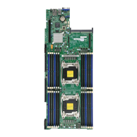
Explanation of Jumpers
To modify the operation of the mother-
board, jumpers can be used to choose
between optional settings. Jumpers cre-
ate shorts between two pins to change
the function of the connector. Pin 1 is
identied with a square solder pad on
the printed circuit board. See the mother-
board layout pages for jumper locations.
Note: On two pin jumpers,
"Closed" means the jumper
is on and "Open" means the
jumper is off the pins.
Pin 1-2 short
3 2 1
3 2 1
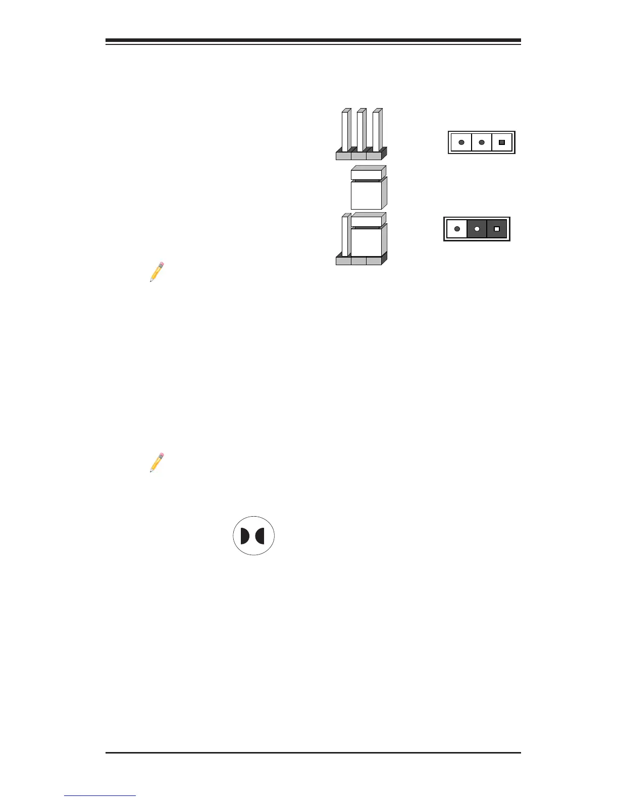
CMOS Clear
JBT1 is used to clear CMOS. Instead of pins, this "jumper" consists of contact pads
to prevent accidental clearing of CMOS. To clear CMOS, use a metal object such
as a small screwdriver to touch both pads at the same time to short the connec-
tion. Always remove the AC power cord from the system before clearing CMOS.
Note: Be sure to remove the onboard CMOS Battery before you short
JBT1 to clear CMOS.
JBT1 contact pads