2-2 Motherboard Installation
All motherboards have standard mounting holes to t different types of chassis.
Make sure that the locations of all the mounting holes for both motherboard and
chassis match. Although a chassis may have both plastic and metal mounting fas-
teners, metal ones are highly recommended because they ground the motherboard
to the chassis. Make sure that the metal standoffs click in or are screwed in tightly.
Then use a screwdriver to secure the motherboard onto the motherboard tray.
User-Supplied Tools & Hardware Needed
Philips Screwdriver
Pan head screws (8 pieces)
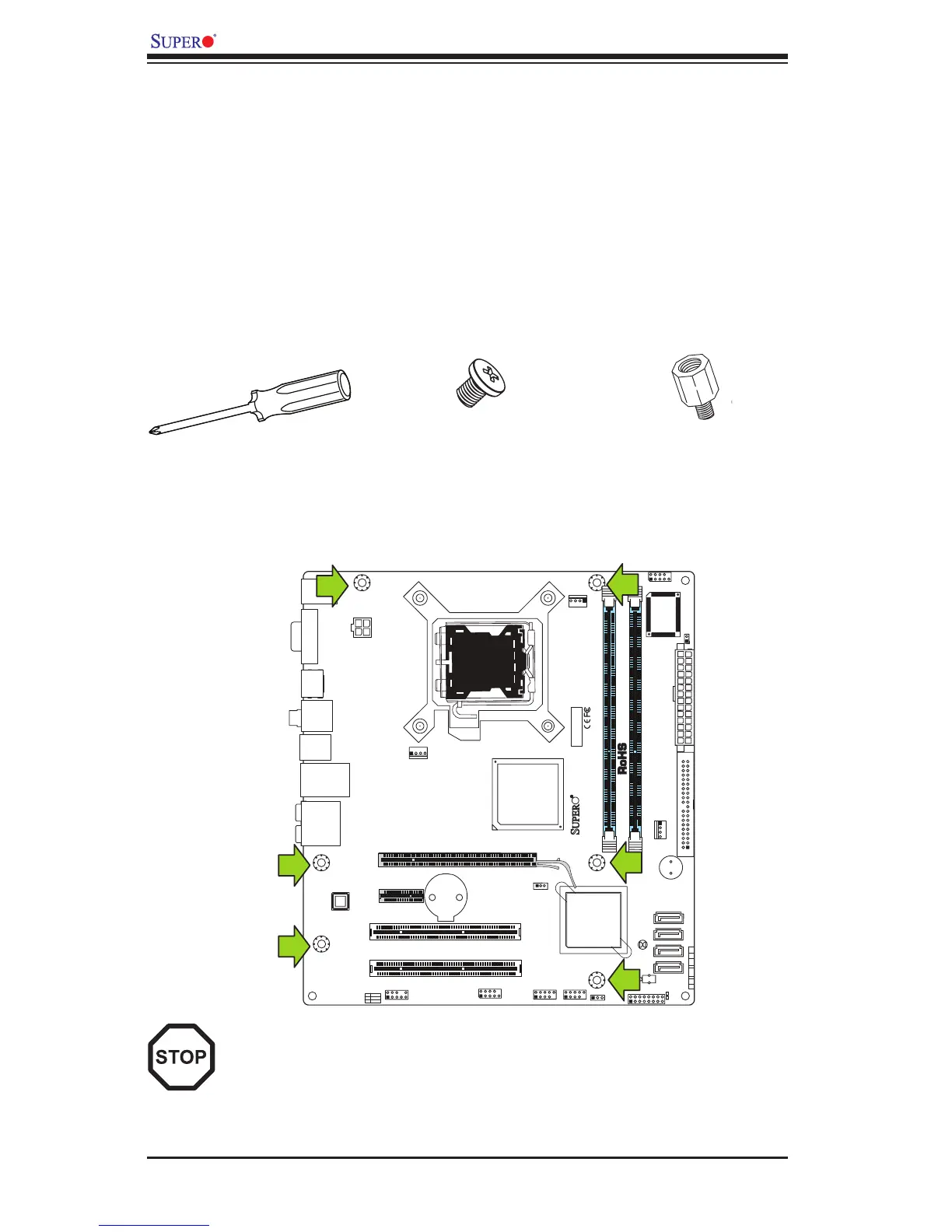
Location of Mounting Holes
There are six (6) mounting holes on this motherboard indicated by the arrows.
Stand Offs (8 pieces)
(Only if needed)
Caution: 1) To avoid damaging the motherboard and its components, please
do not use a force greater than 8 lb/inch on each mounting screw during
motherboard installation. 2) Some components are very close to the mount-
ing holes. Please take precautionary measures to prevent damage to these
components when installing the motherboard to the chassis.