Chapter 2: Installation
2-21
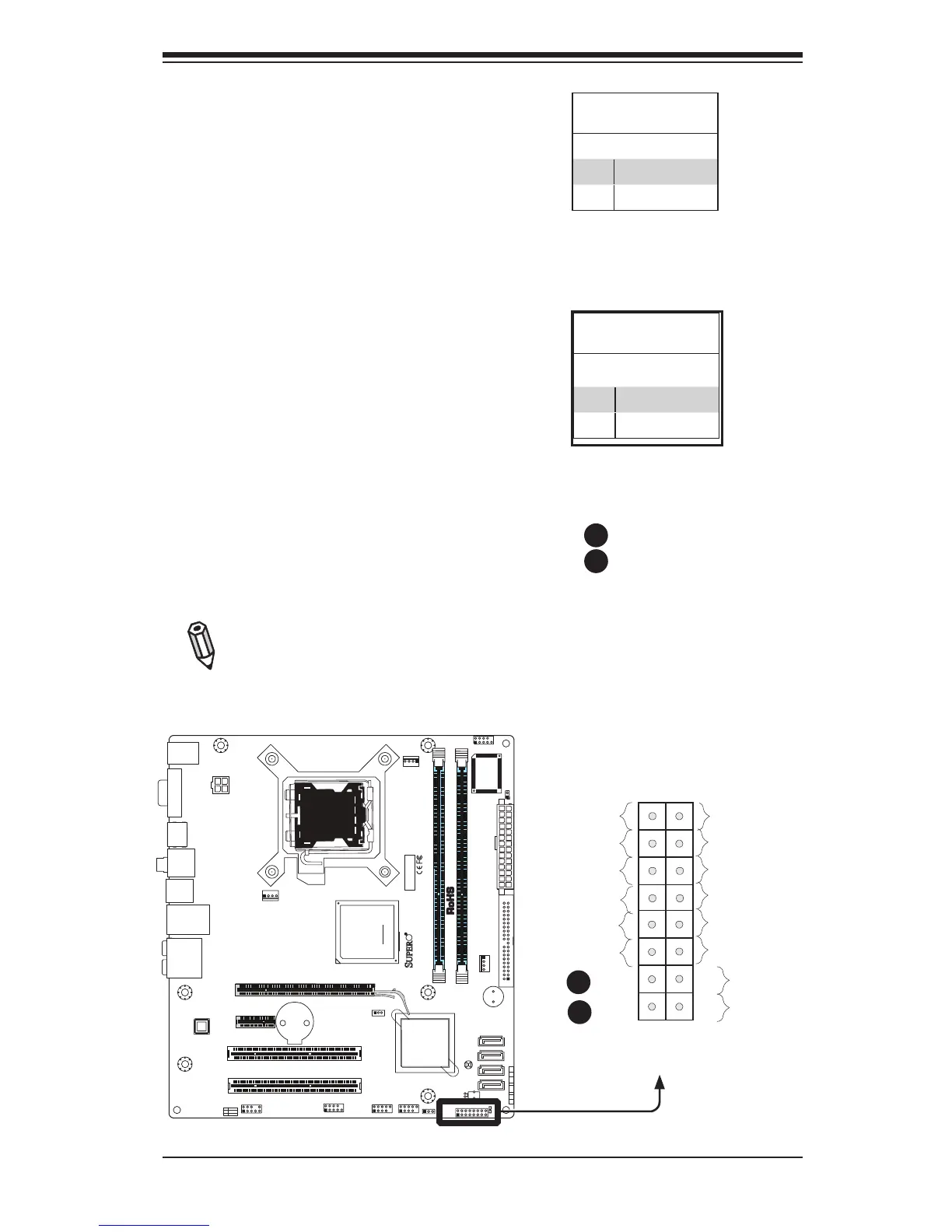
Power Button
The Power Button connection is located
on pins 1 and 2 of JF1. Momentarily con-
tacting both pins will power on/off the sys-
tem. This button can also be congured
to function as a suspend button (with a
setting in the BIOS - see Chapter 4). To
turn off the power when set to suspend
mode, press the button for at least 4
seconds. Refer to the table on the right
for pin denitions.
Note: Do not close or short Pins 1
& 2 since this will cause the system
to continuously reboot.
Power Button
PinDenitions(JF1)
Pin# Denition
1 Signal
2 Ground
Reset Button
The Reset Button connection is located
on pins 3 and 4 of JF1. Attach it to a
hardware reset switch on the computer
case. Refer to the table on the right for
pin denitions.
Reset Button
PinDenitions(JF1)
Pin# Denition
3 Reset
4 Ground
A. Reset
B. PWR Button