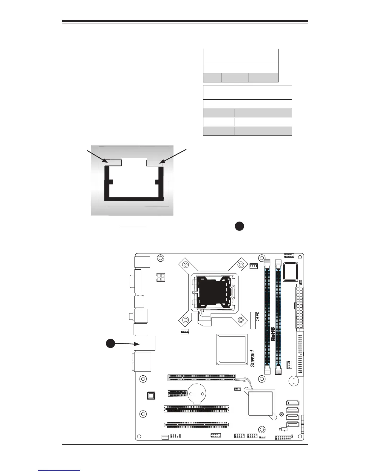
EasyManua.ls Logo

Supero C2G41 - Onboard Indicators

Supero C2G41
93 pages
Print Icon
To Next Page IconTo Next Page
To Previous Page IconTo Previous Page
Loading...
Chapter 2: Installation
2-33
FAN2
FAN1
LE1
JBT1
JF1
121
JPT1
C2G41
Tested to Co mply
With FCC Standards
FOR HOME OR OFFICE USE
AT X_POWER1
LGA775 CPU
AT X12V1
COM2
COM1
1
A
JL1
CHASSIS INTRUSION
TPM
IDE
HDMI
JF1
X
PWR
ON
RST OH/FFX
HDD
NIC1
LED
PWR
LED
CPU FA N
FAN3
I-SATA3
I-SATA2
I-SATA1
I-SATA0
BUZZER
JWOL
+
BATTERY
JPW2
JPW1
AUDIO FP
USB0/1
USB2/3
DIMM1B
DIMM1A
SLOT7 PCI-E X16
SLOT6 PCI-E X1
SLOT5 PCI 33MHZ
SLOT4 PCI 33MHZ
USB6/7 LAN
USB4/5
SPDIF OUT
KB/MOUSE
:CMOS CLEAR
ENABLE
JPT1
1-2
2-3
DISABLE
VGA
PSKBM
AUDIO
GLAN LEDs
There is one Gigabit-LAN port. This Giga-
bit Ethernet LAN port has two LEDs. The
yellow LED indicates activity, while the
Link LED may be green, amber or off to
indicate the speed of the connection. See
the tables at right for more information.
2-8 Onboard Indicators
Activity LED
GLAN Activity Indicator
Color Status Denition
Yellow Flashing Active
GLAN Link Indicator
LED Color Denition
Off No Connection or 10 Mbps
Green (On) 100 Mbps
Amber (On) 1 Gbps
A. GLAN Port1 LEDs
Link
LED
Rear View
(Whenviewingfromtherearside
ofthechassis.)
A
A

Table of Contents

Related product manuals