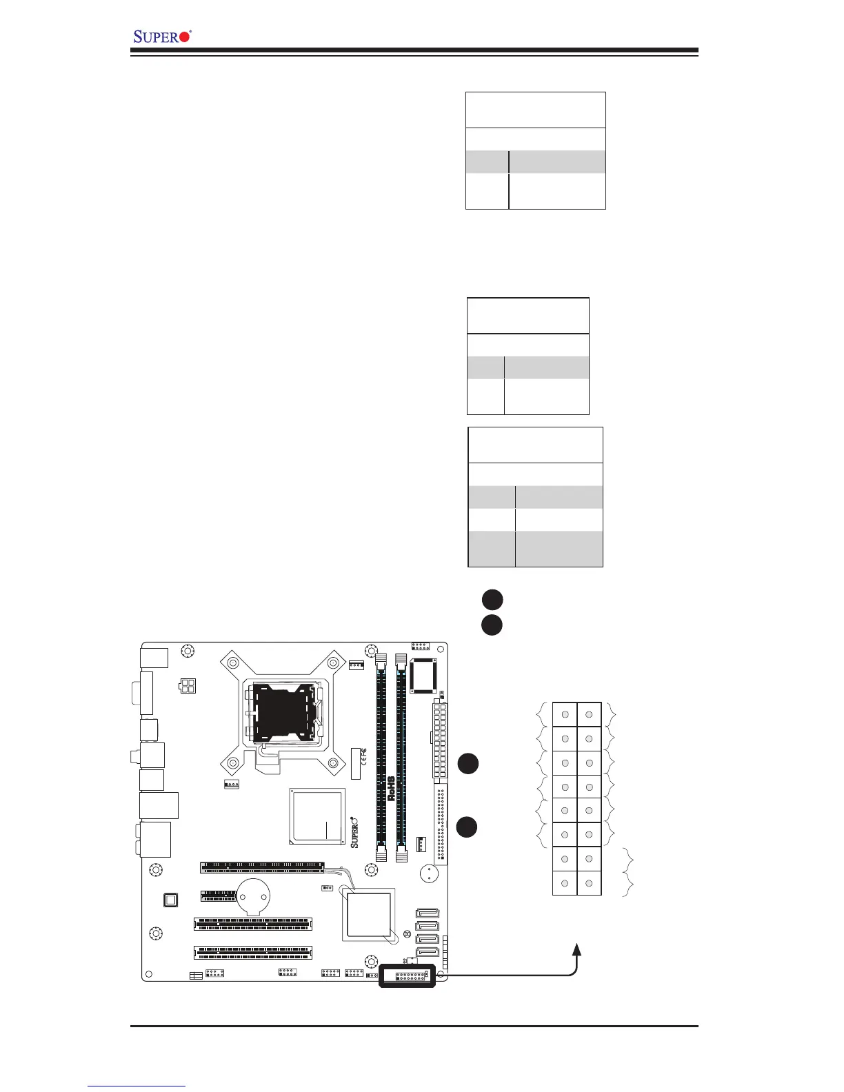
EasyManua.ls Logo

Supero C2G41 - Oh;Fan Fail LED

Supero C2G41
93 pages
Print Icon
To Next Page IconTo Next Page
To Previous Page IconTo Previous Page
Loading...
2-20
C2G41 User's Manual
FAN2
FAN1
LE1
JBT1
JF1
121
JPT1
C2G41
Tested to C omply
With FCC Standards
FOR HOME OR OFFICE USE
AT X_POWER1
LGA775 CPU
AT X12V1
COM2
COM1
1
A
JL1 CHASSIS INTRUSION
TPM
IDE
HDMI
JF1
X
PWR
ON
RST OH/FFX
HDD
NIC1
LED
PWR
LED
CPU FA N
FAN3
I-SATA3
I-SATA2
I-SATA1
I-SATA0
BUZZER
JWOL
+
BATTERY
JPW2
JPW1
AUDIO FP
USB0/1
USB2/3
DIMM1B
DIMM1A
SLOT7 PCI-E X16
SLOT6 PCI-E X1
SLOT5 PCI 33MHZ
SLOT4 PCI 33MHZ
USB6/7 LAN
USB4/5
SPDIF OUT
KB/MOUSE
:CMOS CLEAR
ENABLE
JPT1
1-2
2-3
DISABLE
VGA
PSKBM
AUDIO
NIC1 Indicator
The NIC (Network Interface Control-
ler) LED connection for the GLAN port
is located on pins 11 and 12 of JF1.
Attach the NIC LED cables to display
network activity. Refer to the table on
the right for pin denitions.
GLAN 1 LED
PinDenitions(JF1)
Pin# Denition
11 LED_Anode+
12 NIC1 LED
Signal
A. NIC1 LED
B. OH/Fan Fail LED
Overheat/FanFailLED(OH)
Connect an LED to the OH/Fan Fail
connection on pins 7 and 8 of JF1 to
provide advanced warnings of chassis
overheating or fan failure. Refer to the
table on the right for pin denitions.
OH/Fan Fail LED
PinDenitions(JF1)
Pin# Denition
7 LED_Anode+
8 OH/Fan Fail
LED Signal
OH/Fan Fail Indicator
Status
State Denition
Off Normal
On Overheat
Flash-
ing
Fan Fail
B
A
Power Button
OH/Fan Fail LED
1
NIC1 LED
Reset Button
2
HDD LED
Power LED
Reset
PWR
LED_Anode+
LED_Anode+
LED_Anode+
LED_Anode+
Ground
Ground
X
X
X
X
A
B
JF1 Header Pins

Table of Contents

Related product manuals