2-22
C2G41 User's Manual
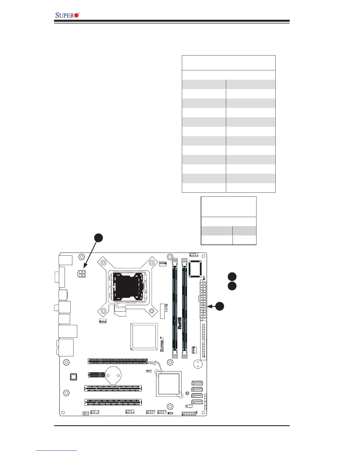
2-6 Connecting Cables
ATX/Auxiliary Power
Connectors
A 24-pin main power connector is lo-
cated at JPW1. This power connector
meets the SSI EPS 12V specica-
tion. See the table on the right for
pin denitions.
ATX Power 24-pin Connector
PinDenitions
Pin# Denition Pin # Denition
13 +3.3V 1 +3.3V
14 -12V 2 +3.3V
15 COM 3 COM
16 PS_ON 4 +5V
17 COM 5 COM
18 COM 6 +5V
19 COM 7 COM
20 Res (NC) 8 PWR_OK
21 +5V 9 5VSB
22 +5V 10 +12V
23 +5V 11 +12V
24 COM 12 +3.3V
12V 4-pin Power Con-
nector
PinDenitions
Pins Denition
1 and 2 Ground
3 and 4 +12V
A
B
4-pin CPU Power Connector
A 4-pin 12V power connector is located
at JPW2 on the motherboard. This
power connector also meets the SSI
EPS 12V specication, and is required
to ensure adequate power to the pro-
cessor. See the table on the right for
pin denitions.
A. 24-pin ATX PWR
B. 4-pin PWR
A
B