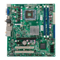
Chapter 2: Installation
2-23
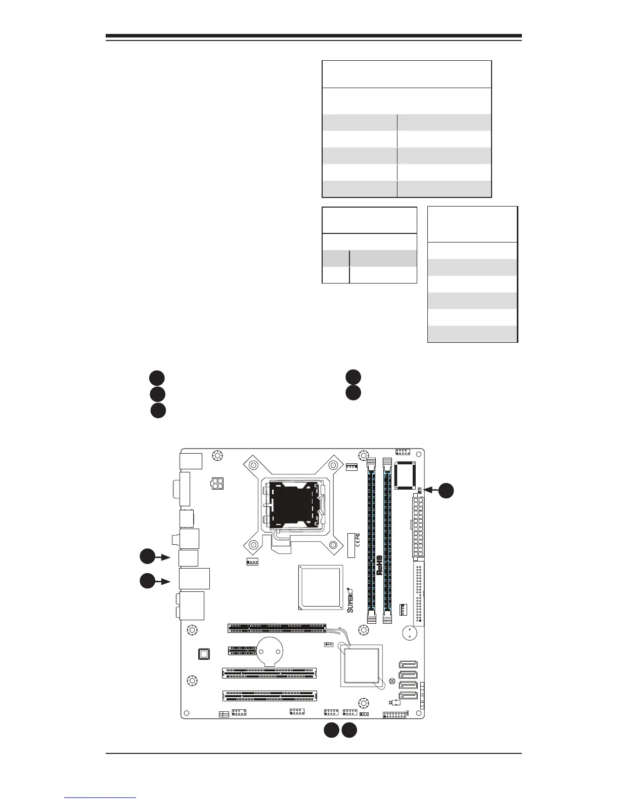
UniversalSerialBus(USB)
There are 8 USB 2.0 (Universal Serial
Bus) ports/headers on the mother-
board. Four of them are Back Panel
USB ports: USB 4/5 and USB 6/7.
The other four are headers that can
be used for front panel connections:
USB 0/1, USB 2/3. See the tables on
the right for pin denitions.
Chassis Intrusion
A Chassis Intrusion header is located
at JL1 on the motherboard. Attach an
appropriate cable from the chassis to
inform you of a chassis intrusion when
it is opened.
Chassis Intrusion
PinDenitions(JL1)
Pin# Denition
1 Intrusion Input
2 Ground
A. Back panel USB Ports 4/5
B. Back panel USB Ports 6/7
C. Front Panel USB 0/1
Back Panel USB
(0-5)
Pin# Denitions
1 +5V
2 PO-
3 PO+
4 Ground
5 N/A
FrontPanelUSB(6/7/8/9)andFront-Ac-
cessibleOnboardUSB(10)Connections
Pin # Denition
Pin # Denition
1 +5V 1 +5V
2 PO- 2 PO-
3 PO+ 3 PO+
4 Ground 4 Ground
5 Key 5 No connection
B
A
D
C
Front Panel USB 2/3
Chassis Intrusion
B
A
D
E
C