9
Section 3 - DRL3 Operating Modes
3.1 DRL3 Standby Mode
After start-up the line card enters the Standby mode
and monitors the telephone line and the CPM3.
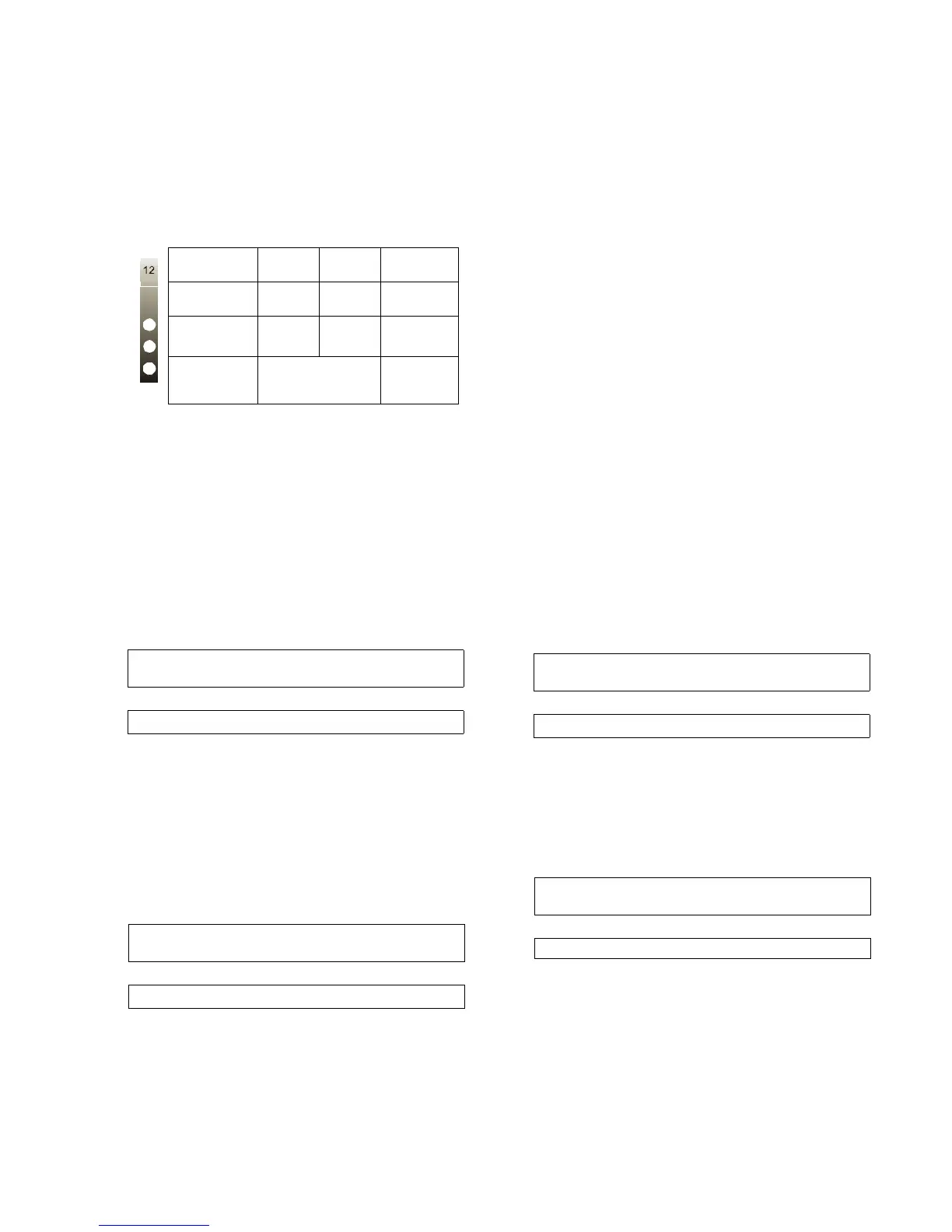
Depending on the system's status, the following con-
ditions will be displayed for each line card:
3.2 Line Fault
The DRL3 verifies the telephone line voltage. The
'Line Fault' LED will come ON when the voltage drops
below 12V
DC.
A hexadecimal number from 01 to 0C representing
the slot number of the line card will be sent for each
'00' shown above.
A hexadecimal number from 01 to 02 representing
the shelf number of the line card will be sent for each
'SS' shown above.
When the line condition returns to normal, the 'Line
Fault' LED will be shut OFF. The following information
will be transmitted to the printer and computer:
NOTE: Additional line fault operation if Backup
Line option is enabled. See Backup Line option
(Option 0E) for explanation.
3.3 CPM3 Error
If the DRL3 cannot detect the CPM3 polling, the
DRL3 will start buffering incoming calls. Up to 512
alarm messages for the printer and computer will be
retained in the DRL3 event buffer. When the event
buffer is full, the line card will stop answering the
calls and the status LED will begin flashing. When the
CPM3 Error condition is corrected, the alarm mes-
sages in the event buffer will be transmitted to the
CPM3 with the corresponding time/date the alarm
has been received.
3.4 Data Reception
During data reception, the yellow STATUS LED will
turn on. The DRL3 decodes all information received
and stores the information in its Event Buffer. When a
valid signal is received, the DRL3 sends a kiss-off sig-
nal and transmits the decoded alarm signal to the
computer and to the printer through the CPM3. The
DRL3 will send each message it receives to the
printer for review by the system operator. Two mes-
sages may be sent to the printer to indicate recep-
tion problems: the 'Fault Data' (Invalid Report) and
'Fault Call' (Communication Fail).
3.4.1 Fault Data Message
When this problem is encountered, the following infor-
mation is transmitted to the printer and the computer:
This output for account code '0000' indicates that
data has been received, but is not valid (for example,
there are unmatched rounds or incorrect parity).
3.4.2 Fault Call Message
When this problem is encountered, the following infor-
mation is transmitted to the printer and the computer:
This output indicates that a call was received, but no
data was detected. The call may have been a wrong
number, or the calling control panel was unable to
connect with the receiver's handshakes.
Computer message NACKed 25 consecutive times.
Printer message: Internal Comm. Error
Computer signal: RRLLL[#0000¦NRTSSOO][DC4]
LED ON OFF FLASH-
ING
LINE
(Red)
Line
Fault
Line
Normal
N/A
STATUS
(Yellow)
On-line Off-line
*Error
condition
WATCH-
DOG
(Blue)
Line Card
not functional
Line Card
functional
* The number of flashes on the yellow LED
indicates the following errors:
1. CPM absent
2. Line card clock not set
3. EBUS command to disable the line card
was sent.
4. Printer or computer buffer full.
5. Checksum failed when downloading
Flash ROM files.
Printer:
Jul 17 1998-08:08:28-SS/OO-SG-RR-LLL-0000-
PHONE LINE TROUBLE
Computer:
0RRLLL[#0000¦NLTSSOO][DC4]
Printer:
Jul 17 1998-08:08:35-SS/OO-SG-RR-LLL-0000-
PHONE LINE RESTORE
Computer:
0RRLLL[#0000¦NLRSSOO][DC4]
Printer:
Jun 25 1998-11:18:07-SS/OO-SG-12-234-0000-
INVALID REPORT
Computer:
012234[#0000¦NYNSSOO][DC4]
Printer:
Jun 25 1998-11:18:07-SS/OO-SG-12-234-0000-
COMMUNICATION FAIL
Computer:
012234[#0000¦NYCSSOO] [DC4]