3
The DRL3 receives ANI (Automatic Number Identifi-
cation) and/or DNIS (Dialed Number Identification
Service) via the Telco connection. This information
allows the Sur-Gard expert format identification sys-
tem to change options on the fly for each received
call. This eliminates dedicated line pool hardware.
The DNIS information is used in a look-up table,
which sets up virtual line pools to identify security
formats and extend account numbers. Standard
dialed number identification is supported up to 10
digits. Each dialed number would have formerly been
a line pool on conventional line cards.
1.3.7 BP3X Interface Module
(optional - one required per rack)
This 19” Rack mounted panel interfaces with the
System III Telco connector to provide 24 RJ-11 con-
nectors for direct connection to telephone lines.
NOTE: On the BPX3 the B ports are the channels
used for two-way audio or back-up telephone line.
Figure 1-3 Front
• Parallel Printer: A standard parallel printer output is located
on the back of the CPM3.
For UL Listed applications, the following UL listed printers
can be used with the System III:
- Sur-Gard CPU-1150 - DMP SCS-PTR
- Sur-Gard CPU DMP-206 - Seiko DPU-414
• Serial Printer
: A standard serial printer output is located on the
back of the MLRF3.
For UL Listed applications, the following UL listed printers can
be used with the System III: Seiko DPU-414
IMPORTANT: Do not use a printer cable that has only 1
common ground wire.
NOTE: Non-printable characters are replaced by a square
on the print out. Ensure that the printer is configured for
80 columns (System III only supports 80 columns).
• Connections for Redundant System III: Refer to Figure 1-7
System III Redundancy Wiring Diagram.
• CPM3 Debug Output: Connect the RJ-45 end of the debug
cable to the debug output jack.
Connect the female DB-9 connector to the serial port of a
computer (COM1 port - usually DB-9 male).
Figure 1-4 CPM3 Debug Cable
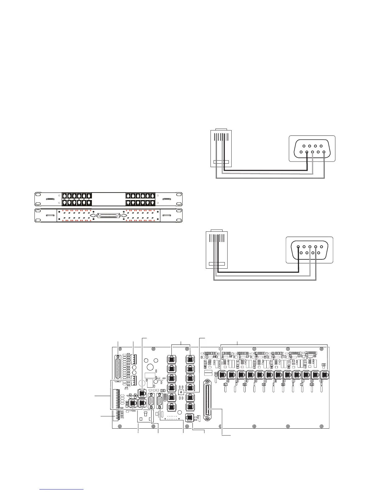
• DRL3 Debug Output: Connect the RJ-45 end of the debug
cable to the debug output jack on the front of the line card.
Connect the female DB-9 connector to the serial port of a
computer (COM1 port - usually DB-9 male).
Figure 1-5 DRL3 Debug Cable
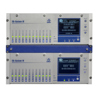
• IEC Power Connector: Provides local power line connection
(cable is not supplied).
Figure 1-6, System III Wiring Diagram
A A
B B
6 5 4 3 2 1
BP3X
54321
8
976
RJ45
Back of DB9
1 2 3 4 5 6 7 8
Pin 2 to Pin 5
Pin 5 to Pin 3
Pin 6 to Pin 2
12345
7
689
RJ45
Back of DB9
1 2 3 4 5 6 7 8
Pin 3 to Pin 2
Pin 4 to Pin 3
Pin 5 to Pin 5
DB25
Parallel
Printer
Output
Not
Used
CPM3
Debug
Output
IEC Power
Connector
120Vac / 60 Hz*
2.5A
RS-232
Serial
Printer
Output
Ethernet**
Output
10/100 BaseT
25 Pair RJ-21 Supervised Telephone Lines
(Refer to Appendix C for pin out)
0
1
2
3
4
5
8
6
7
9
A
B
D
C
E
F
12 RJ-45
Connectors
Not Used
Shelf
Address
Switch
12 RJ-45
Connectors
Not Used
All circuits
are power
limited
Note: Maintain 6.5mm (1/4") separation between
power limited and non-power limited circuits.
Note: All external
devices should be
mounted in the same
room as the receiver.
RS-232
Serial
Automation
Output
* For Model System III CE:
- 240V
AC /50Hz
- System III CE is not UL Listed
**CAUTION: The ethernet
communication lines must be
connected first to an Approved
(acceptable to the local
authorities) type NID (Network
Interface Device) before leaving
the premises (e.g., UL
installations, UL60950 Listed
NID).
Connections for second
backplane
See System III Supervised
UPS Connection Diagram for
details
Note: For UL Installations:
- AC input is 120V
AC / 60 Hz.
- Do not connect to a receptacle
controlled by a switch.