4
WARNING! To reduce the risk of electric shock the prod-
uct is provided with a grounding type power supply IEC
recepticle. Connect product using an appropriate IEC
cable to a grounded recepticle.
• RS-232 Serial Automation Output: Provides serial connec-
tion to a local computer running automation software. A
straight through serial cable must be used.
• RS-232 Serial Printer Output: Provides serial connection to
a local computer or serial printer.
• 25 Pair Telco Connection: Connects directly to the local PBX
or to BP3X-3 (Refer to Appendix C for pinouts).
• Ethernet Output 10/100 BaseT: Traditional automation
communication is provided via port 1025 on the Ethernet
connection. This primary port is a Sur-Gard standard output
and provides Sur-Gard standard automation protocol out-
put. All or a number of virtual receiver types can be mapped
to the Sur-Gard output.
CAUTION: The ethernet communication lines must
be connected first to an Approved (acceptable to
the local authorities) type NID (Network Interface
Device) before leaving the premises (e.g., UL
installations, UL60950 Listed NID).
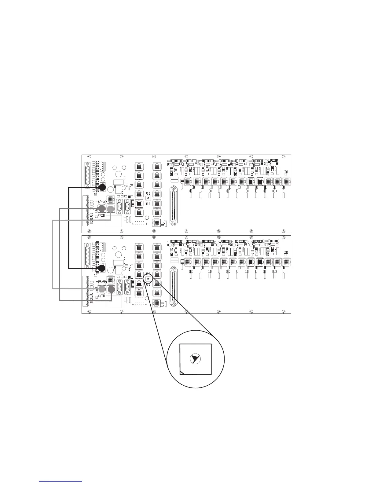
Figure 1-7, System III Redundancy Wiring Diagram
0
1
2
3
4
5
8
6
7
9
A
B
D
C
E
F
0
1
2
3
4
5
8
6
7
9
A
B
D
C
E
F
Use a small flat screw
driver to turn the shelf
address switch to 2 on
the second redundant
System III.
Shelf 2
Shelf 1
0
1
2
3
4
5
8
6
7
9
A
B
D
C
E
F
Use only the cables provided in the
System III Interconnect Pack. Failure
to do so may result in damage to the
unit. Using the provided RJ-45 patch
cables connect the Output of the
primary System III (shelf address 1)
to the Input of the redundant system
III (shelf address 2). Connect the
Output of the redundant System III to
the Input of the primary System III.
All circuits are power limited