Introduction
2
1.4 Receiver Setup and Operation
DSC recommends testing the receiver before actual installation.
Becoming familiar with the connections and setup of the unit on the
workbench will make final installation more straightforward. The
following items are required:
• IEC Power supply cord
• One network hub or router
• One or more dialer or digital control panel and a T-LINK TL250/
TL300
1. Unpack the components for the System III.
NOTE:
Carefully unpack the receiver and inspect for shipping
damage. If there is any apparent damage, notify the carrier imme-
diately.
2. Unscrew the front thumb screws and open the front
plates.
NOTE:
Before inserting the CPM3, connect the ribbon cable from
the UIB3 board. Before inserting the PSC3 connect the LCD back-
light.
3. Insert all the cards in the rack, in their appropriate position.
Refer to Figure 1-2 in the System III Installation Manual.
Connect the ribbon cable of the front panel to the CPM3
before inserting it. Connect the backlight power connec-
tion to the PSC3 then insert the PSC3.
4. Insert the PSU3 into the rack and fasten it properly.
5. Connect an ethernet cable to the proper line card.
6. Connect the main power (110V
AC or 220VAC) using a
standard computer IEC cable (not supplied).
7. The LCD will power up and display internal troubles
(printer, computer, telephone line fault, network absent).
The SG-DRL3-IP Receiver will have the green LED ON if the
ethernet line is connected. If the LED is not on, make sure
the ethernet line is connected to the right port
.
NOTE: Internal diagnostics may require more than one minute
during the power up sequence.
8. Send a signal from a control panel to the receiver. The sig-
nal will be displayed on the LCD. Press the [ACK] button to
silence the buzzer.
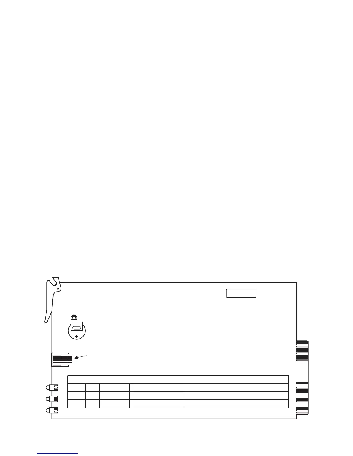
F D K
UA 424
CON1
RS232 Driver Debug
J1
LED 1 GRN Line Fault Network Absence On if network is present
LED 2 YEL
S
tatus Trouble Condition(s) Indicates Trouble by number of blinks
LED 3
BLU Watch Dog
Software Watch Dog Toggles every 500mS.
LED Indicators
Figure 1, SG-DRL3-IP Layout