Introduction
3
NOTE: When a hub or router/gateway is used in conjunction with the
System III receiver, 24-hr standby power is required for these devices
(i.e., UL Listed UPS, battery backup or engine driven generator).
1.5 Description (Operation)
1.5.1 Operation with Default Programming
Without any changes to the factory default programming, the
receiver operates as indicated below:
• The signals are sent to the parallel printer and computer con-
nected to serial port COM1 or to the 10/100BaseT connector.
• If a computer is not connected, press the [ACK] button on the
CPM3 to silence the buzzer and to clear the alarm from the
LCD display.
1.5.2 Virtual Connectivity
Each receiver has one IP address and a number of associated ports.
Internal socket programming uses specific ports for expected tasks.
The configuration management, done from the Console Software, is
located on port 1024. The System III Console software is provided
for Windows 98/ME/NT/2000/XP, which provides a graphical style
menu for configuration management. Additional features are avail-
able with the console software including storage of virtual receiver
setups, and configuration wizards.
1.5.3 Status Addressing
Line card status is reported via physical addressing. Shelf and slot
number are assigned automatically to each line card. All device status
information is in Sur-Gard format. The reporting of status on this port,
automation output and printer will relate to physical addressing.
1.5.4 Automation input/output (Port 1025)
Traditional automation communication is provided via port 1025 on
the Ethernet connection. This primary port is a Sur-Gard standard
output and provides Sur-Gard standard automation output. All or a
number of virtual receiver types could be mapped to the Sur-Gard
output.
1.5.5 Automation Protocols
The Sur-Gard System III receiver sends a variety of protocols to report
signals to the central station computer via a TCP/IP and/or RS-232
port. A complete list of protocols can be provided upon request.
1.5.6 Data Byte Protocol
The Sur-Gard System III receiver uses a default configuration of 9600
Baud rate, 1-start bit, 8-data bits, 0-parity bits and 2-stop bits struc-
ture, to transmit and receive signals on the RS-232 port. This proto-
col can be programmed on the receiver to enable different
configurations.
1.5.7 Acknowledgment of the Signal
The Sur-Gard System III receiver requires an acknowledgment signal
[ACK] (Hex 06) from the computer software within 4 seconds for
each message sent. Failure to receive the [ACK] will result in 3
retransmissions of the signal before indicating a communication fail-
ure. During a communication failure the System III receiver will cease
transmitting except for the heartbeat. The same thing happens if the
receiver receives a [NAK] (Hex 15). In case of communication failure
with the computer, the System III DRL3 line card can store up to 512
events and the DRL3-IP line card can store up to 768 events in the
line card internal memory. Communication is resumed when the first
acknowledgment is received on the heartbeat; all buffered informa-
tion is then transmitted.
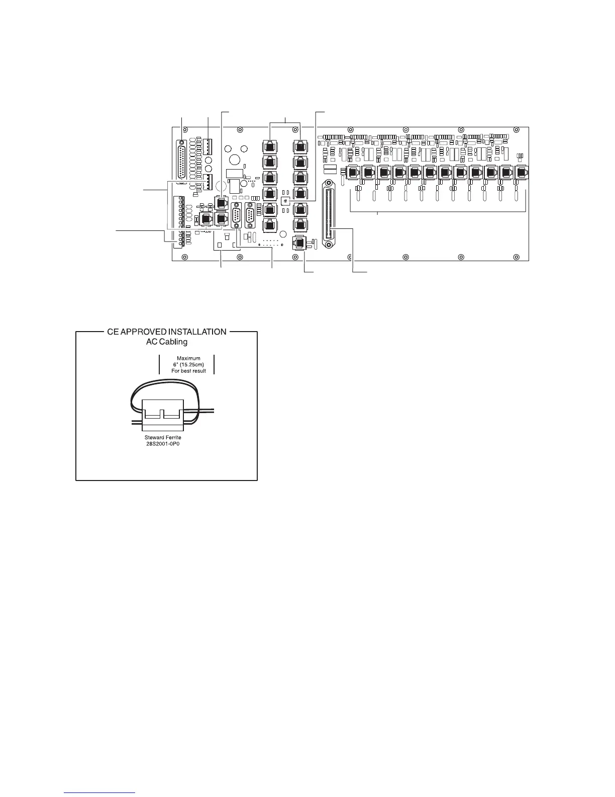
Figure 2, System III Wiring Diagram
DB25
Parallel
Printer
Output
Not
Used
CPM3
Debug
Output
See System III
Supervised UPS
Connection Diagram
for details
Connections for
second backplane
IEC Power
Connector
120V
2.5A
AC/60Hz*
RS-232
Serial
Automation
Output
Ethernet
Output
10/100 BaseT
25 Pair RJ-21 Supervised Telephone Lines
(Refer to Appendix C for pin out)
0
1
2
3
4
5
8
6
7
9
A
B
D
C
E
F
12 RJ-45
Connectors
Not Used
Shelf
Address
Switch
(12) RJ-45 Ethernet Connectors
For use with SG-DRL3-IP only
Note: Maintain 6.5mm (1/4") separation between
power limited and non-power limited circuits.
Note: For UL Installations
AC input is 120V 60Hz.
Do not connect to a receptacle
controlled by a switch.
AC/
* For Model System III CE: 240V /50Hz
System III CE is not UL Listed.
AC
Notes: Mount external devices in the
same room as the receiver.
All circuits are power limited
RJ-45
Socket
DRL3-IP
Network
Place the ferrite clamp and the Ethernet CAT5 cables
inside the 19” cabinet where the System III receiver is
installed.