6-40 ELECTRICAL SYSTEM
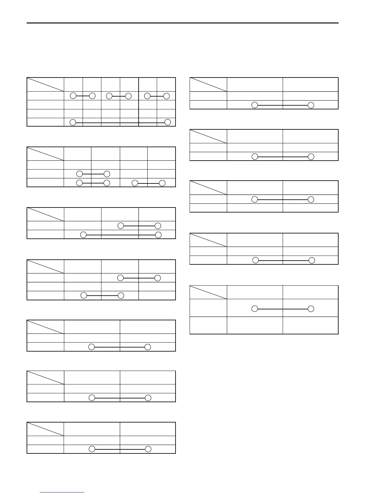
IGNITION SWITCH
R O O/Y B/W Gr Br
ON
OFF
LOCK
P
LIGHTING SWITCH (except for E-03, 28, 33)
O/Bl Gr O/R Y/W
OFF (1)
(2)
ON (3)
DIMMER SWITCH
W Y Y/W
HI (4)
LO (5)
TURN SIGNAL SWITCH
Lg Lbl B
L (6)
PUSH
R (7)
PASSING LIGHT SWITCH (except for E-03, 28, 33)
O/R Y
1
PUSH
ENGINE STOP SWITCH
O/B O/W
OFF (8)
RUN (9)
STARTER BUTTON
O/W Y/G
1
PUSH
SWITCHES
Measure each switch for continuity using a tester. If any abnormality is found, replace the respective switch
assemblies with new ones.
HORN BUTTON
B/Bl B/W
1
PUSH
FRONT BRAKE LIGHT SWITCH
B/R B/Bl
OFF
ON
REAR BRAKE LIGHT SWITCH
O/G W/B
ON
OFF
CLUTCH LEVER POSITION SWITCH
B/Y B/Y
FREE
1
OIL PRESSURE SWITCH
G/Y Ground
ON (engine
is stopped)
OFF (engine
is running)
NOTE:
Before inspecting the oil pressure switch, check if
the engine oil is at the proper level. (
!
2-9)
WIRE COLOR
B : Black Lbl: Light blue R : Red
Br : Brown Lg : Light green Y : Yellow
Gr : Gray O : Orange W : White
B/Bl : Black with Blue tracer O/G : Orange with Green tracer
B/R : Black with Red tracer O/R : Orange with Red tracer
B/Y : Black with Yellow tracer O/W : Orange with White
tracer
B/W : Black with White tracer O/Y : Orange with Yellow tracer
G/Y : Green with Yellow tracer W/B : White with Black tracer
O/B : Orange with Black tracer Y/G : Yellow with Green tracer
O/Bl: Orange with Blue tracer Y/W: Yellow with White tracer
Color
Position
Color
Position
Color
Position
Color
Position
Color
Position
Color
Position
Color
Position
Color
Position
Color
Position
Color
Position
Color
Position
Color
Position
 Loading...


