4-8 FUEL SYSTEM
CARBURETOR
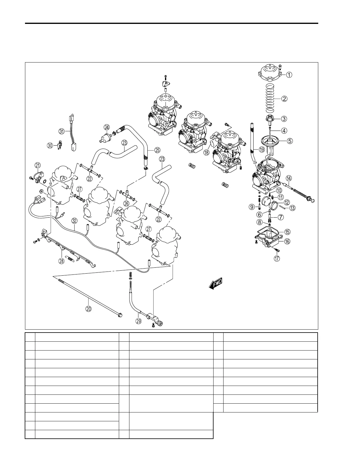
CONSTRUCTION
1 To p c a p
C Float pin
M Air vent hose
2 Spring
D Starter (enricher) plunger
N Fuel filter
3 Jet needle stopper
E Gasket (O-ring)
O Fuel hose
4 Jet needle
F Float chamber
P Fuel joint pipe No. 1
5 Diaphragm/Piston valve
G Drain screw
Q Fuel joint pipe No. 2
6 Needle jet
H Vacuum inlet cap
R Starter (enricher) plate
7 Needle jet holder
I Vacuum hose (for fuel valve)
S Throttle stop screw
8 Main jet
J
Carburetor set shaft
(Upper and Lower)
T Carburetor heater (For E-02, 19)
9 Pilot screw
U Thermo-switch (For E-02, 19)
0 Slow jet
K
TPS
(Throttle position sensor)
A Needle valve assy
B Float
L Air vent joint pipe
 Loading...


