Brake Control System and Diagnosis: 4A-1
Brake
Brake Control System and Diagnosis
Schematic and Routing Diagram
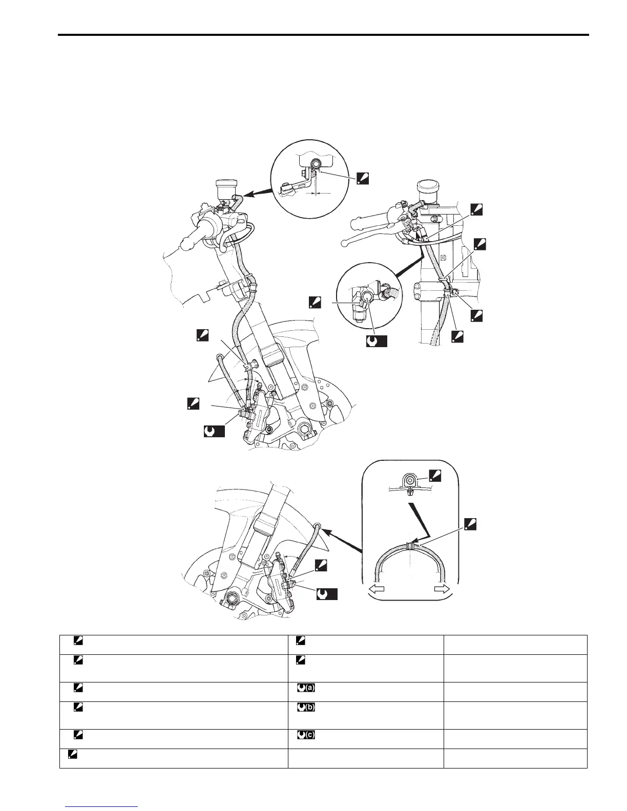
Front Brake Hose Routing Diagram
B837H14102001
1
2
2
3
4
5
2
“a”
“b”
“c”
“d”
“B”
“B”
“A”
“C”
(a)
(b)
(c)
RHLH
I837H1410054-03
1. Hose clamp
: Clamp end should face downward.
“B”: Clamp the brake hose firmly. “b”: 15°
2. Stopper
: After the brake hose union has contacted to the stopper,
tighten the union bolt.
“C”: Pass the brake hose through rear
side of the throttle cables.
“c”: 40°
3. Hose guide
: Pass the brake hose through the hose guide.
: 23 N⋅m (2.3 kgf-m, 16.5 lb-ft) “d”: 40°
4. Stopper
: After positioning the clamp with the stopper, tighten the
clamp bolt.
: 23 N⋅m (2.3 kgf-m, 16.5 lb-ft)
5. Hose clamp
: Insert the clamp end into the hole on the front fender.
: 23 N⋅m (2.3 kgf-m, 16.5 lb-ft)
“A”: White marking
: White marking should be on right side and face upward.
“a”: 1 – 2 mm (0.04 – 0.08 in)

 Loading...