Contents
Homepage
3. Fuel System
Mechanism Diagram ·················3-1
Precautions in Operation ·········3-2
Troubleshooting························3-3
Carburetor Removal··················3-4
Throttle Valve ····························3-6
Float Chamber / Jet Set ············ 3-6
Carburetor Installation·············· 3-8
Air Cut-off Valve························ 3-9
Idle Speed Adjustment ············· 3-10
Fuel Tank ··································· 3-11
Air Cleaner································· 3-13
3
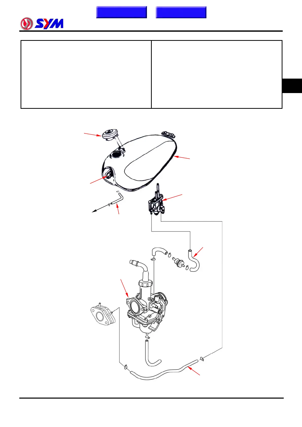
Mechanism Diagram
Fuel tank cap
Fuel Tank
Air Cut-off Valve
Vacuum type
fuel cock
To the Carbon
canister
Fuel Vapor
Collector
Fuel outlet tube
Carburetor
Vacuum
tube
3-1