Do you have a question about the Symmetricom 9611B and is the answer not in the manual?
| Brand | Symmetricom |
|---|---|
| Model | 9611B |
| Category | Switch |
| Language | English |
Details copyright, warranty terms, and conditions for hardware and software.
Outlines limitations of liability and provides contact information for support.
Lists document revisions and how to reach customer assistance.
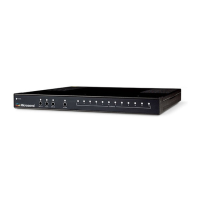
Introduces the 9611B Switch & Distribution Unit, its function, and a typical application diagram.
Covers receiving inspection, rack mounting, and making connections.
Details turning the system on, default values, installation warnings, and chassis grounding.
Addresses VAC power connector, dangerous voltages, and AC power switching.
Provides specific guidelines for electrical installations in Norway and Sweden.
Explains basic operation, manual switching, and auto-switching logic including arming.
Presents a simplified block diagram and lists key hardware components.
Describes the function of front panel LEDs (POWER, INPUT A, AUTO, INPUT B, ALARM) and pushbuttons.
Details the connectors and their purposes on the rear panel of the unit.
Covers fault detection, timecode, 1PPS, RF signal switching, and remote management.
Details the two external alarm inputs accessed via rear panel BNC connectors.
Explains the alarm output relay contact and field jumper configuration for RF gain.
Provides detailed descriptions of front panel LEDs and pushbutton actions for operation.
Guides on connecting via serial port, CLI parameters, and general command usage.
Lists CE, UL, and FCC compliance standards for emissions, immunity, and safety.
Details specifications for RF, Pulse/DC IRIG, and AM IRIG time code signal inputs.
Covers specifications for RF outputs, additive phase noise, and Pulse/DC IRIG outputs.
Describes the specifications and configuration for alarm inputs.
Outlines system status features and Electromagnetic Compatibility (EMC) standards.
Details RoHS compliance, operating/storage environmental specifications, and installation over-voltage category.
Describes the chassis, front panel, and rear panel physical layouts.
Lists the unit’s dimensions and power supply requirements.
