Basic Operation and Features
SimplifiedBlockDiagram
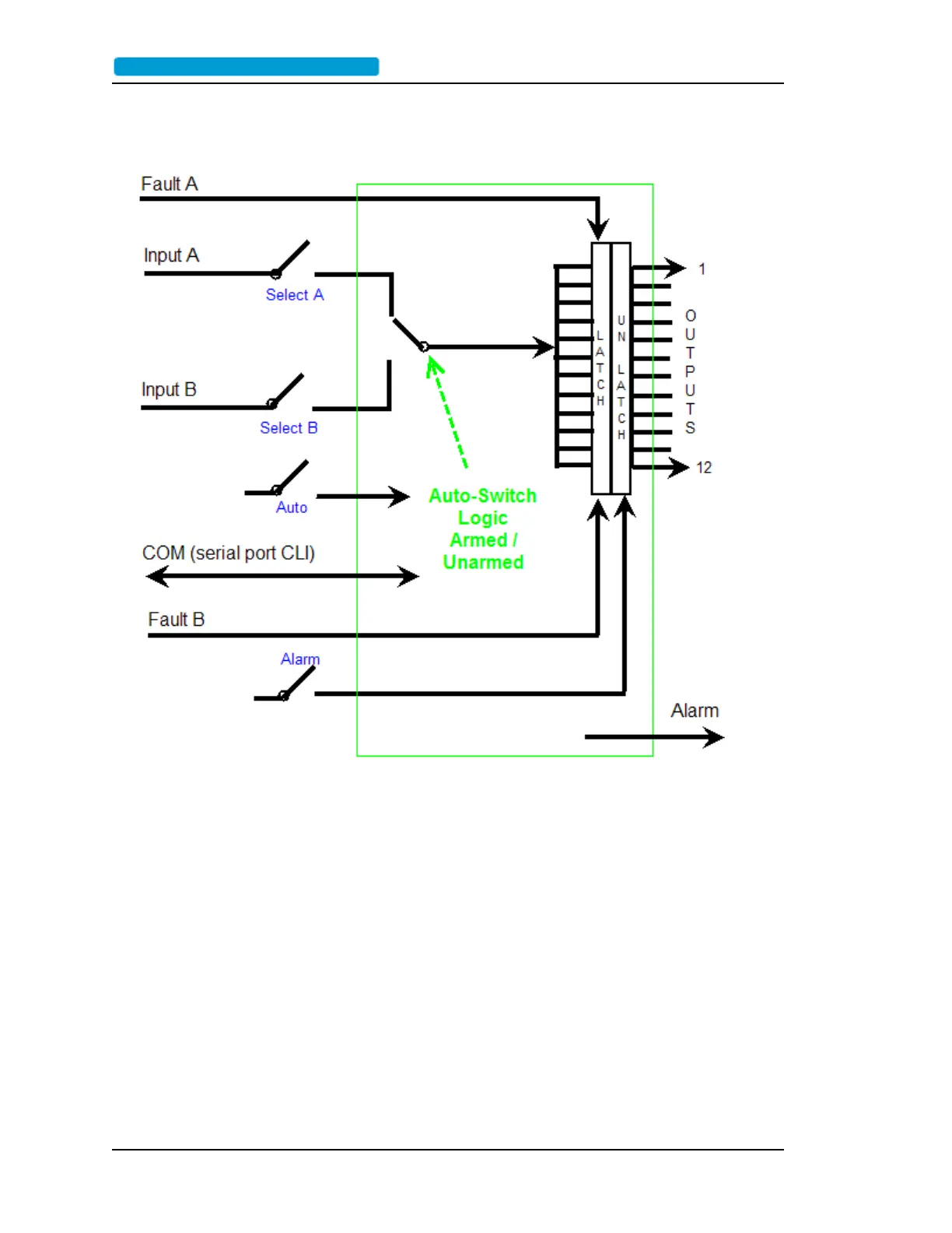
In the simplified block diagram, the 9611B has:
l 2 selectable signal inputs (A and B)
l 2 Alarm inputs (A and B)
l 12 outputs (1-12)
l Alarm relay output
l Serial RS232 port command line interface (CLI)
In addition, to the inputs and outputs, there are two other front panel switches:
l Auto switch for arming the A/B signal input switch.
l Alarm switch for resetting the latched alarms.
The heart of the 9611B is the auto-switch logic. This logic monitors the conditions above, including the
command line interface. Depending on the conditions, the auto-switch logic switches the A/B signal
input accordingly, and drives the CLI and front panel LEDs.
Page 8 ..........................................................................9611B_UserGuide_RevA.pdf
 Loading...