LED
label
Green
(solid)
Green
(slow
flash)
Red
(solid)
Red
(slow
flash)
Red
(fast
flash)
Amber
(solid)
Amber
(slow
flash)
Off
Input B, or
ALARM to return
Input B to
green.
Input B, or
ALARM to
return Input
B to green.
ALARM n/a n/a
Fault
identified
n/a n/a See 1 below
Output
1-12
Signal
detected
on output
n/a Fault
detected
on out-
put.
n/a n/a Output had a
fault which is
now gone.Press
ALARM to return
this to green.
See 1 below
Note 1 If the power LED is green and all of the other LEDs are OFF, the 9611B is in the bootloader
mode. Also, see the reset command..
Table 2: Front Panel Pushbuttons
Pushbutton Action Result
Press INPUT A (left button) Selects INPUT A
Press AUTO (center button) Autoswitch mode*
Press INPUT B (right button) Selects INPUT B
Press ALARM Unlatches the alarm state, turns off the red alarm LED and toggles the alarm
relay contacts. If an ALARMcontinues to exist, the ALARM is reset after the appro-
priate timeout interval.
Press and hold ALARM for 10 seconds Resets product configuration to its factory default settings.
* See Autoswitch Interface section for a full description of autoswitch indicators and functions
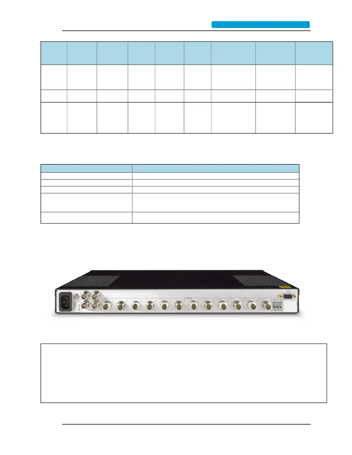
RearPanel
Figure 3: Rear Panel
Table 3: Table of Rear Connectors
Connector Name Purpose
# of
connections
Connector
type
Power AC power input 1 IEC 320
Alarm Relay Three terminal relay contacts, NO, COM, and NC for alarm conditions. 1 Screw Terminal
COM Provide for a serial command line interface 1 DB-9
9611B_UserGuide_RevA.pdf.......................................................................... Page 11
 Loading...