Basic Operation and Features
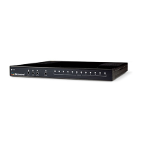
Figure 4: Field Jumper Configuration
The RF gain can be adjusted with the P2 jumper field settings shown above in its default setting.
On the 9611B printed circuit board is a jumper field header with an associated label. The label shows
positions of A B C D E, with A positioned at the diamond (pin1) on the header.
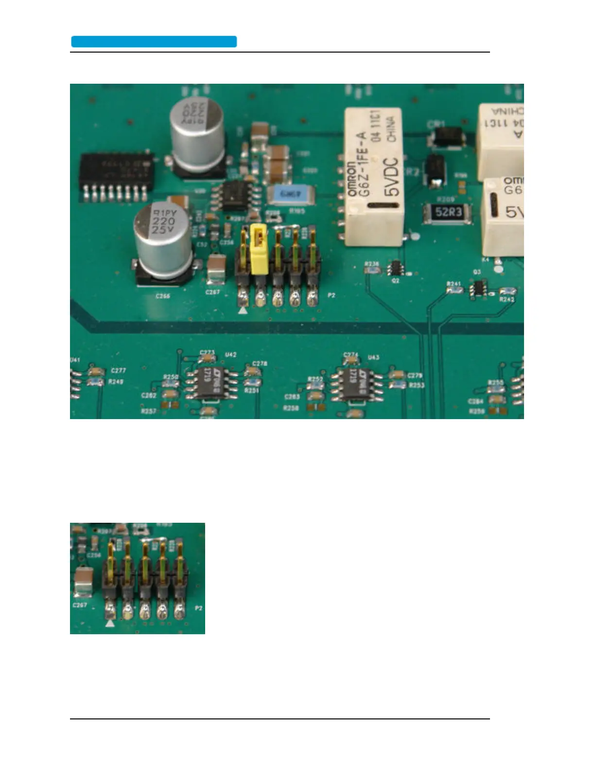
Figure 5: Lowest gain
(-3dB) is no jumper
Page 18 ..........................................................................9611B_UserGuide_RevA.pdf
 Loading...