Status
Mechanical
Chassis
l 1U, 19 inch rack mount
Note: Use four (4) 10--32 machine screws to secure front mounting flanges to rack.
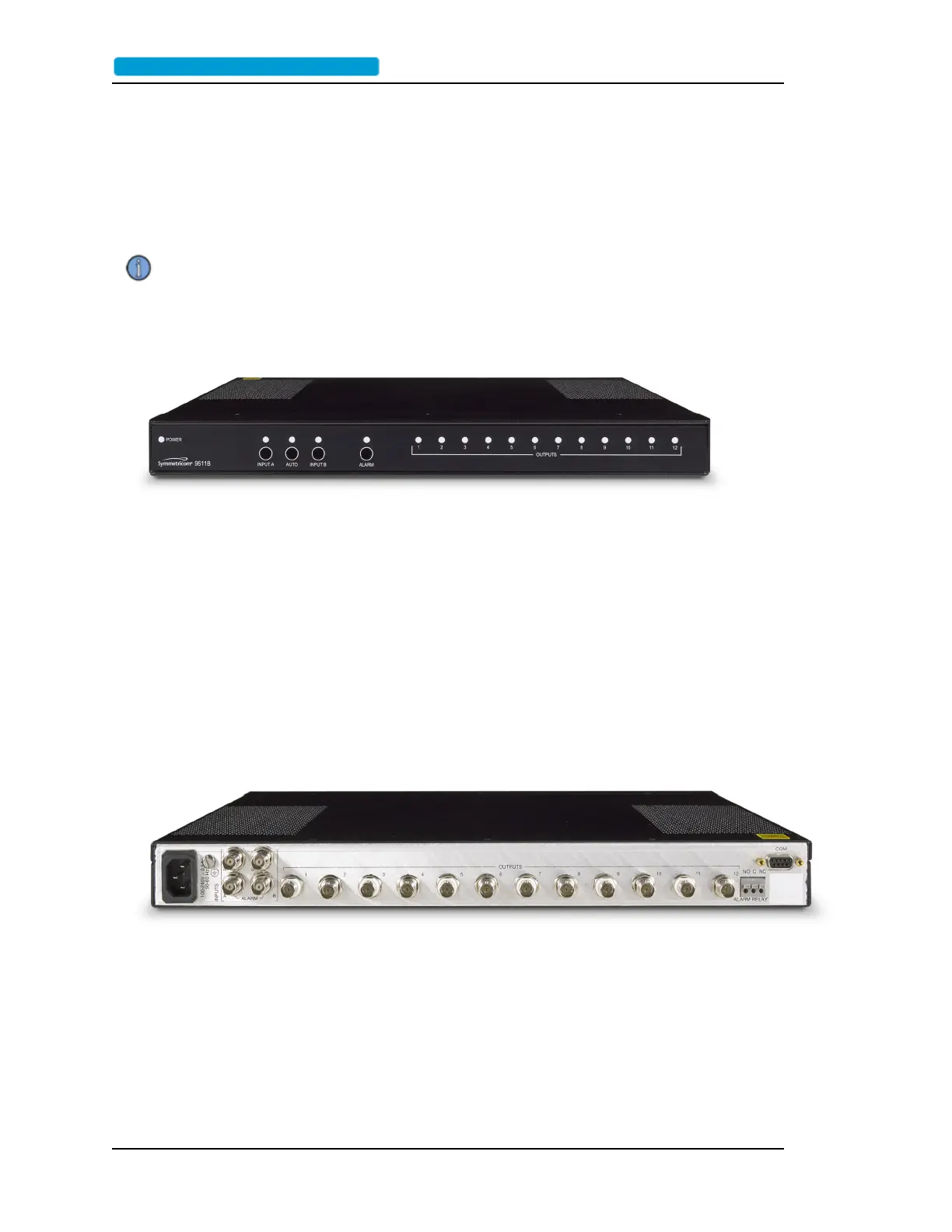
FrontPanel
l 1 each, power LED labeled POWER (Green)
l 3 each, autoswitch LED, labeled INPUT A, AUTO and INPUT B (Tri-color: Green, Red,
Amber)
l 12 each, output signal LEDs, labeled 1 through 12 (Tri-color: Green, Red, Amber)
l 1 each, alarm LED, labeled ALARM (Red)
l 3 each, momentary-contact autoswitch pushbuttons, 1 ea. under the INPUT A, AUTO and
INPUT B LEDs
l 1 each, momentary-contact alarm-clearing pushbutton under the ALARM LED
RearPanel
l Rear Panel
l 2 each, input signal BNC connectors, labeled INPUT A and INPUT B
l 2 each, TTL alarm input BNC connectors, labeled ALARM A and ALARM B
l 1 each, AC power connector
l 1 each, earth ground screwterminal
l 1 each,. Female DB9 Standard Serial CLI Port, labeled COM
Page 42 ..........................................................................9611B_UserGuide_RevA.pdf
 Loading...