SA 160
AIRCRAFTA I R C R A F T
Symphony
AIRCRAFT
(1) Description
The VM 1000 Indicator
A data processing unit (DPU) receives electrical signals generated
from different engine sensors. The DPU output is connected with
the VM 1000 indicator (See Fig. 7-6), the EC 100 system (See Fig. 7-
7), and when installed, with a digital clock and an OAT / CAT
indicator.
The VM 1000 Indicator is located on the right section of instrument
paneladjacenttotheradios.
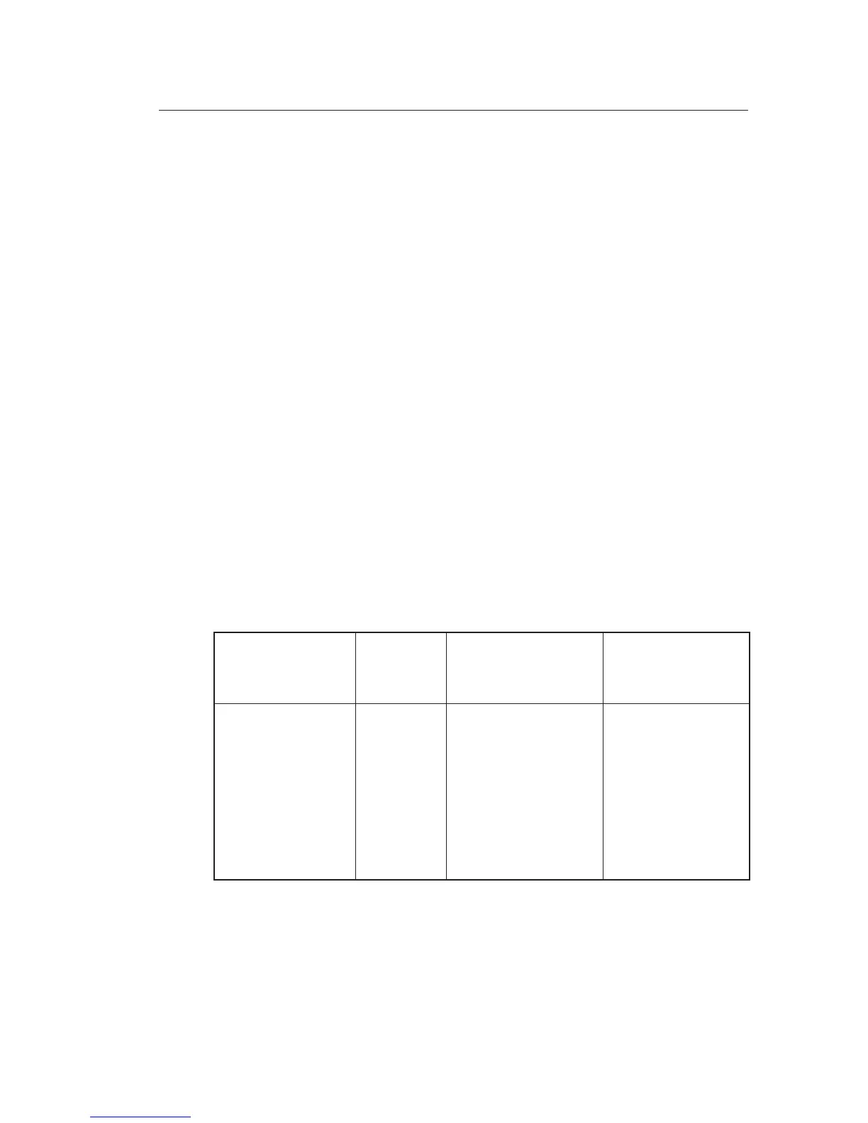
Table 7-1 shows the displayed engine parameters, the units, the
full sweep graphic display resolution, and the incremental steps of
thedigitalreadout.
Color markings of operating ranges, caution ranges, and
prohibited ranges are described in Section 2 “Limitations”.
(SeeFig.7-5)
Parameter
Unit
Graphic Display
Resolution
Digit. Display
Incremental Steps
Man Pressure in.HG 1’’ IN. HG 0.01 IN.HG
Engine Speed RPM Proportional 10 RPM
Fuel Pressure PSI Proportional 0.1 PSI
Oil Pressure PSI Proportional 1 PSI
Oil Temperature °F Proportional 1 °F
Voltage V Proportional 0.1 V
Amperage A Proportional 1 A
CHT °F N.A. 1 °F
EGT °F N.A. 1° F
Table 7-1
VM 1000 - Display parameters
SECTION 7
DESCR. & OPERATION
7-21
Feb 25, 2005