124 Disassembly and Reassembly TP9100 Service Manual
© Tait Electronics Limited May 2005
2. Place the top seal D over the power/volume potentiometer, 16-
way/3-way selector switch, and antenna SMA connector.
3. Fit the main keypad
F to the inside of the front-panel assembly G.
Ensure that the outside edge of the keypad sits correctly inside the
groove of the front-panel assembly.
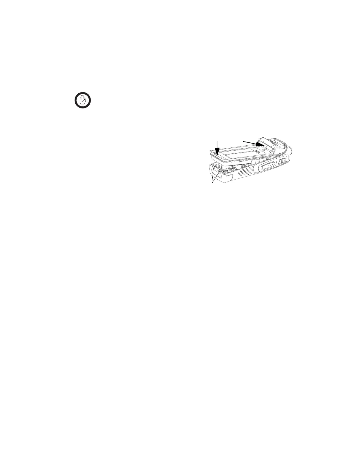
4. To insert the chassis assembly into the front-panel assembly:
Important When pushing the chassis assembly into the front-panel
assembly, check by looking through the battery lug holes,
that the main seal
E is not displaced at the base near the
battery lugs.
a. Insert the top components of
the chassis assembly through
the holes of the front-panel
assembly.
b. Push and hold the chassis
assembly towards the top (
B)
and carefully push the chassis
into the bottom of the front-
panel assembly (
C).
5. Look through the holes in the top of the front-panel assembly and
check whether the top seal
D is placed correctly around the
power/volume potentiometer, 16-way/3-way selector switch, and
antenna SMA connector
6. Use a Torx T6 torque-driver to tighten the two screws
D to 3lb·in
(0.34N·m).
battery lug holes
B
c
3671z_01

 Loading...


