EasyManua.ls Logo

Tascam 388 Studio 8 - Head Alignment; Reel Tabla Height Adjustment

Tascam 388 Studio 8
139 pages
Print Icon
To Next Page IconTo Next Page
To Previous Page IconTo Previous Page
Loading...
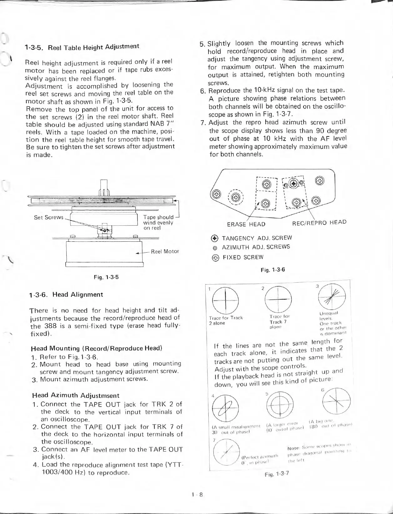
1-3-5.
Reel
Table
Height
Adjustment
Reel
height
adjustment
is
requlred
only
If
a
reel
motor
has
been
replaced
or
if
tape
rubs
exces-
sively
against
the
reel
flanges.
Adjustment
is
accomplished
by
loosening
the
reel
set
screws
and
moving
the
reel
table
on
the
motor
shaft
as
shown
¡n
Fig.
1-3-5.
Remove
the
top
panel
of
the
unit
for
access
to
the
set
screws
(2)
in
the
reel
motor
shaft.
Reel
table
should
be
adjusted
using
standard
NAB
7"
reels.
With
a
tape
loaded
on
the
machine,
posi-
tion
the
reel
table
height
forsmooth
tapetravel.
Be
sure
to
tighten
the
set
screws
after
adjustment
is
made.
5.
Siightiy
loosen
the
mounting
screws
which
hold
record/reproduce
head
in
place
and
adjust
the
tangency
using
adjustment
screw,
for
máximum
output.
When
the
máximum
output
is
attained,
retighten
both
mounting
screws.
6.
Reproduce
the
10-kHz
signal
on
the
test
tape.
A
picture
showing
phase
relations
between
both
channeis
will
be
obtained
on
the
oscillo-
scope
as
shown
in
Fig.
1-3-7.
7.
Adjust
the
repro
head
azimuth
screw
until
the
scope
dlsplay
shows
less
than
90
degree
out
of
phase
at
10
kHz
with
the
AF
level
meter
showing
approximately
máximum
valué
for
both
channels.
Set
Screws
Tape
should
wind
evenly
on
reel
Reel
Motor
Fig.
1-3-5
1-3-6.
Head
Alignment
There
is
no
need
for
head
height
and
tilt
ad-
justments
because
the
record/reproduce
head
of
the
388
is
a
semi-fixed
type
{erase
head
fully-
fixed).
Head
Mounting
(Record/Reproduce
Head)
1.
Refer
to
Fig.
1
-3-6.
2.
Mount
head
to
head
base
using
mounting
screw
and
mount
tangency
adjustment
screw.
3.
Mount
azimuth
adjustment
screws.
Head
Azimuth
Adjustmsent
1.
Connect
the
TAPE
OUT
jack
for
TRK
2
of
the
deck
to
the
vertical
input
termináis
of
an
oscilloscope.
2.
Connect
the
TAPE
OUT
jack
for
TRK
7
of
the
deck
to
the
horizontal
input
termináis
of
the
oscilloscope.
3.
Connect
an
AF
level
meter
to
the
TAPE
OUT
jack(s).
4.
Load
the
reproduce
alignment
test
tape
{YTT-
1003/400
Hz)
to
reproduce.
ERASE
HEAD
REC/REPRO
HEAD
(¥)
TANGENCY
ADJ.
SCREW
©
AZIMUTH
ADJ.
SCREWS
FiXED
SCREW
Fig.
1-3-6
Trace
for
Track
2
alone
Trace
for
Track
7
alone
If
the
Unes
are
not
the
same
each
track
alone,
it
indicates
tracksarenot
putting
out
the
Adjust
with
the
scope
controls.
If
the
playback
head
is
not
strai
down
you
willseethiskindoT
Unequal
levels-
One
track
or
the
other
is
dommant.
length
for
that
the
2
same
level.
ght
up
and
picture:
^—
(A
bit)
one.
(Asman
m,salignn.ent
180
olh
of
pbase)
30
out
of
phase)
=0
0
Note.
Somescüpes
show
-n
d.aqonal
pomtmq
to
(Perlect
azimuth
pnas
O'
.
inphitsel
the
left

Table of Contents