GTS Technical Manual
5. March 2013 Edition: V1.10/2013 5-40
Copyright © 2013, Diversey Inc.
05.42.10 lower part - castor wheel - 455B_455E_755B eco_755E_755B power_855B power_V1.00.fm
5.7 Lower part
5.7.1 Removing of castor wheel
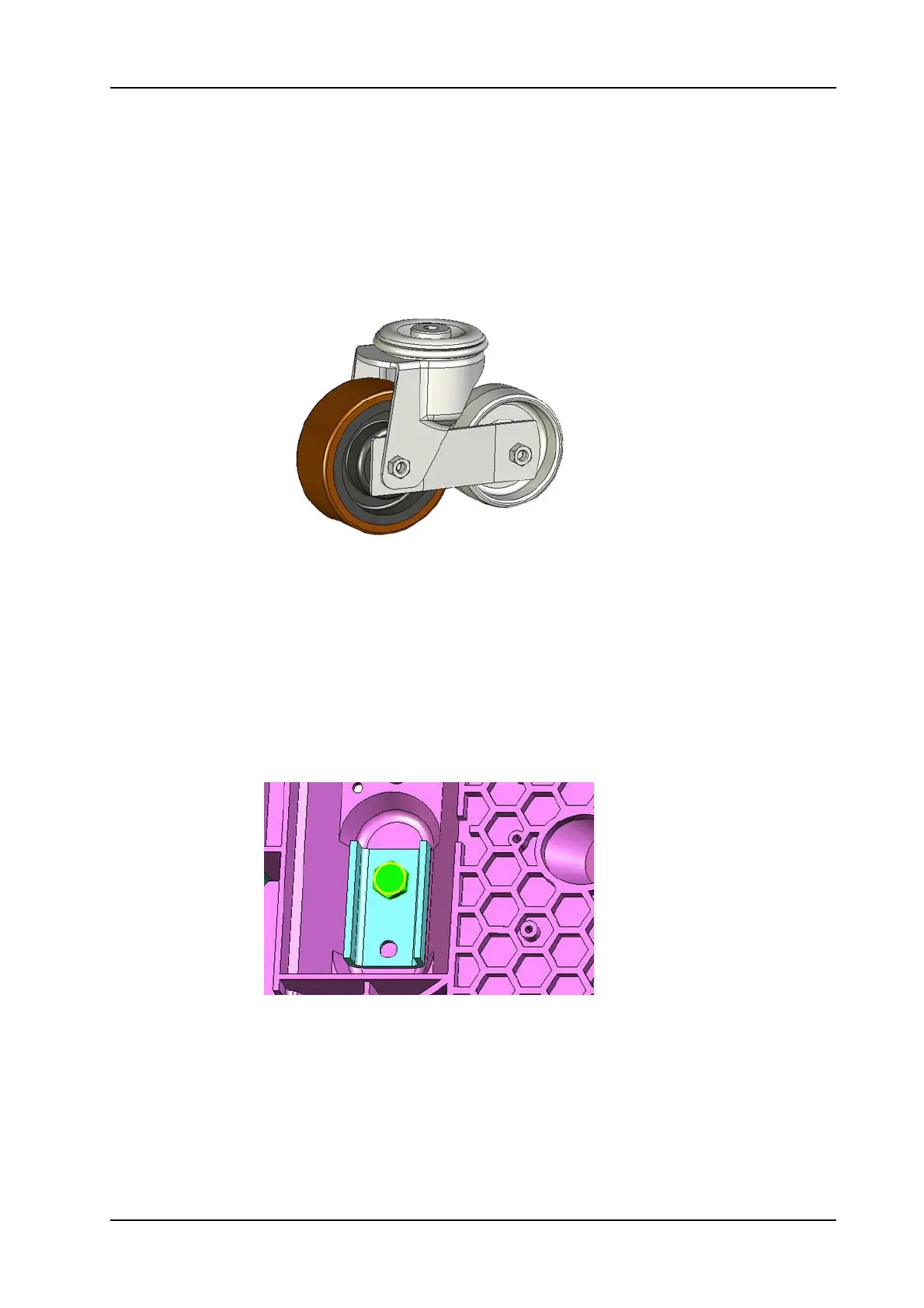
Picture 61: Castor wheel
• Unlock battery compartment on the LH side by removing the
screw (455:02/122, 755B:09/114, 755E:09/110) from the
locking system.
• Lay the machine on the LH side.
• Unlock battery compartment on the RH side by removing the
screw from the locking system.
• Open the battery compartment.
• Untighten the fixation screw (455:07/103, 755B:05/104,
755E:06/117) with a 19 mm fork spanner.
Picture 62: Castor wheel screw
• Remove the complete castor wheel (455:07/124, 755B:05/115,
755E:06/125) and squeegee support.
 Loading...