ROTEX 600 XTPRO: Service & Maintenance Manual - rev. 1.1
Page 7.11
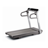
7.10. DISASSEMBLING THE ELECTRONIC CIRCUIT BOARDS
Figure 7.10-1
Carry out the procedure described in paragraph
7.7. “Disassembling the frame guards”.
1. On each side, back off the 2 nuts a using a
10-mm wrench.
2. Unscrew the 3 screws b using a medium
Phillips screwdriver.
3. Open the guard of the ELECTRONIC
CIRCUIT BOARD group.
4. Disconnect the 3 connectors of the cables
going to the ELECTRONIC CIRCUIT
BOARD group.
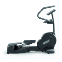
Figure 7.10-2
To disassemble the POWER SUPPLY c:
1. Disconnect the 2 connectors CN1 and CN2.
2. Disconnect the grounding fast on.
3. Unscrew the 4 screws fixing it to the support
plate using a 7-mm socket wrench.
4. Remove the circuit board.
To disassemble the ALTERNATOR
INTERFACE BOARD d:
1. Disconnect the 3 connectors CN1, CN2 and
CN3.
2. Remove the 4 screws fixing it to the support
plate using a 7-mm socket wrench.
3. Remove the circuit board.
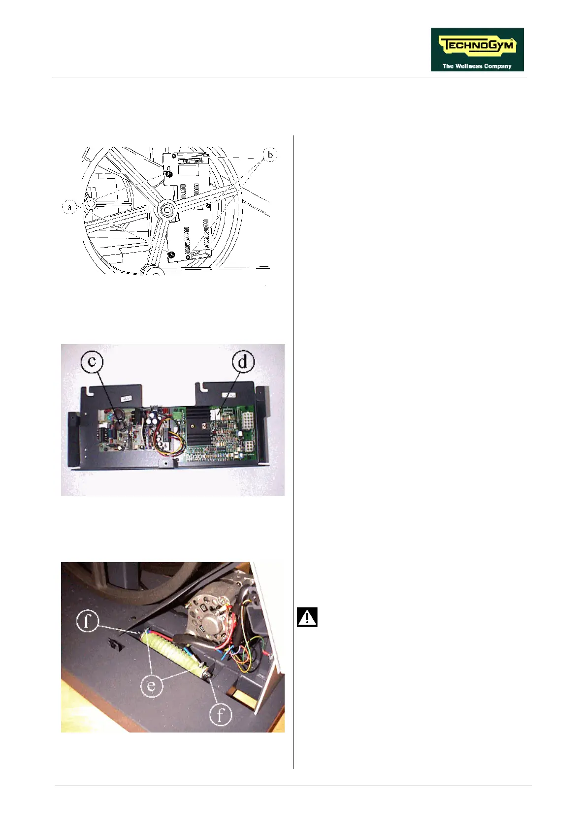
Figure 7.10-3
To disassemble the POWER RESISTOR,
situated underneath the alternator:
Check that the resistor is not hot.
1. Unscrew the 2 locknuts of cable RT-5 using a
7-mm wrench and disconnect the 2 cables.
2. Unscrew the 2 locknuts of the resistor using a
10-mm wrench.
3. Remove the resistor.
To reassemble the ELECTRONIC CIRCUIT
BOARDS, carry out the above steps in reverse
order.