Maintenance
3. Disconnect the
Main board power cable from the Combiner board. (See
Figure 3-10 on page 3-16.)
4. Disconnect the two power cables from J10 and J 20 on the Combiner board.
(See Figure 3-14 on page 3-20.)
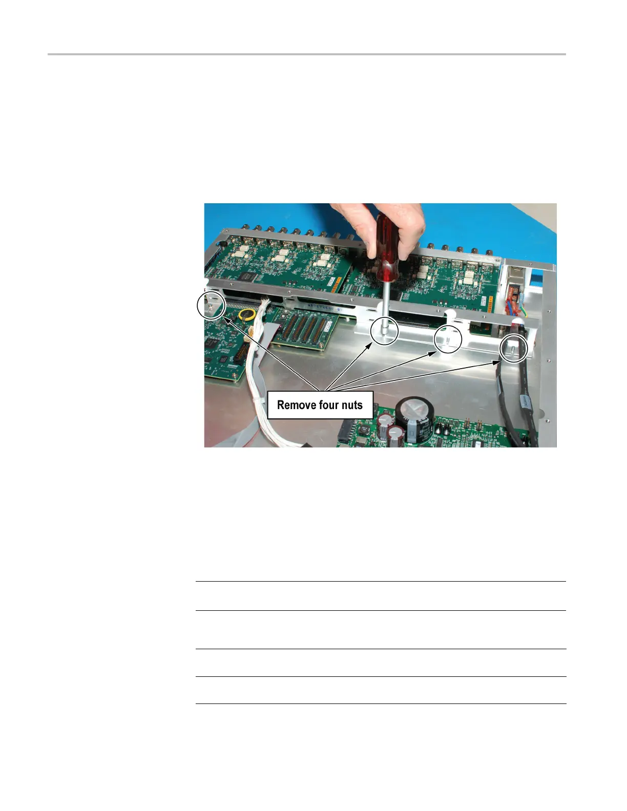
5. Use a 6 mm nut driver (7/32 inch may also work) to remove the four nuts
securing the support b racket to the bottom of the chassis (reassembly torque:
4.0 in/lb.).
Figure 3-6: Removing the circuit board support bracket
6. Lift the bracket up and away from the chassis while carefully sliding the
three power cables through the slots in the bracket. Move the bracket so
that it is out of the way of accessing the channel modules, and is not sitting
on any circuit boards.
7. Use the appropriate tool (see table below) to rem
ove the nut/lock washers or
screws from the rear-panel of the channel module that you are removing.
NOTE. You do not need to remove upper channel modules to remove a lower
channel module. You can remove each module individually.
Channel module Connector type Connector removal tool
ECO8000: REF/ELSW,
HREF/Relay
BNC 9/16 inch deep nut driver
Reassembly torque: 14 in/lb.
ECO8020: REF/ELSW,
HREF/Relay
HD BNC
P2 screwdriver
Reassembly torque: 4.0 in/lb.
3–12 ECO8000 Series Service Manual

 Loading...
