Maintenance
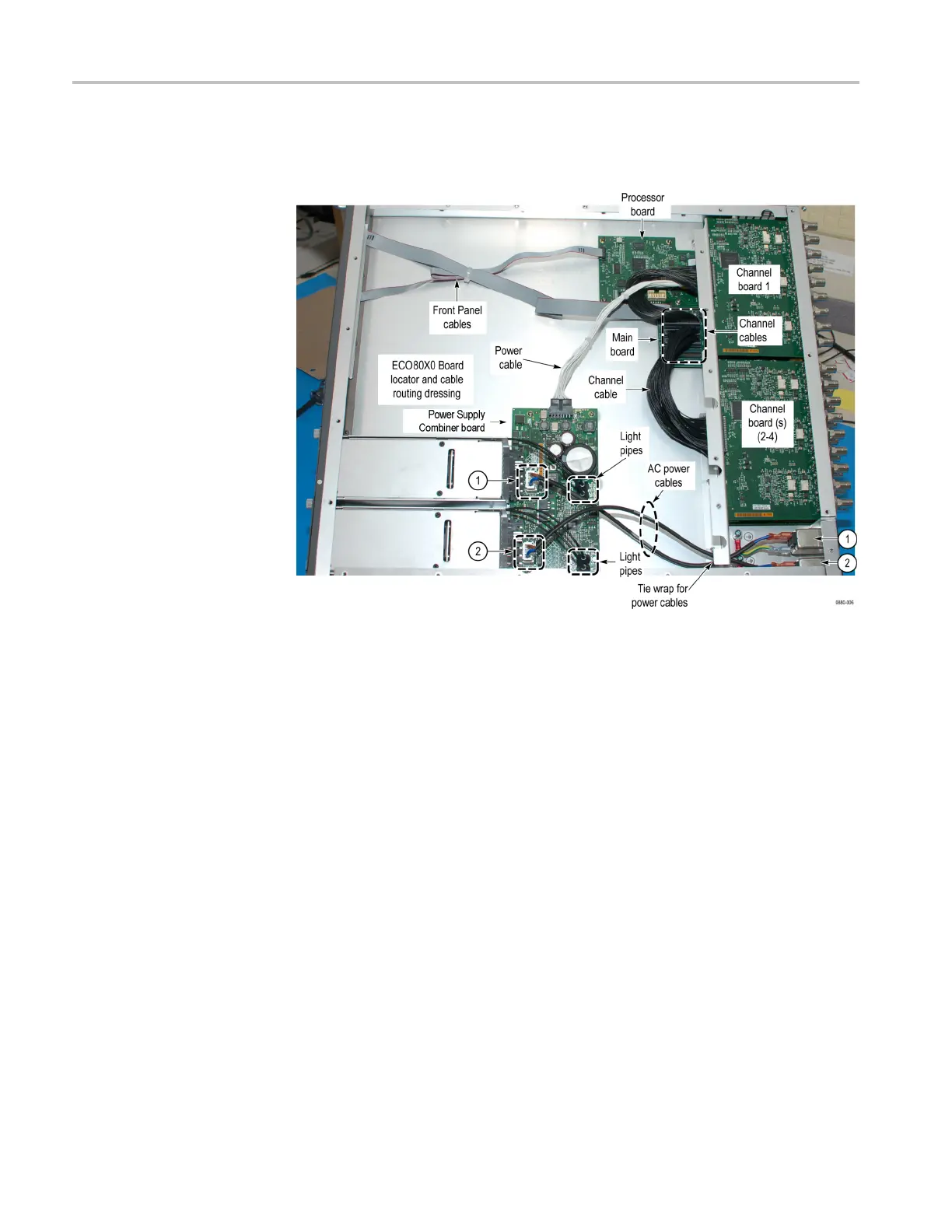
Board locator and cable
type/routing
Use the followi
ng to identify instrument board locations and cables, and to
correctly route cables when a ssembling.
Figure 3-3: Board locator and cable routing diagram
Remove the Processor
board
1. Disco
nnect the narrow ribbon d isplay cable from J1 of the Processor board.
2. Remove the 4 screws on the Proces sor board (reassembly torque: 4.0 in/lb.).
3. Lift the back edge of the Processor board slightly and carefully pull away
from the rear panel to disconnect the Processor board from the main board.
Reassembly. Reassemble in the reverse order of the disassembly procedure.
3–10 ECO8000 Series Service Manual

 Loading...
