Maintenance
Reassembly. As
semble in the reverse order of the disassembly procedure. The
following areas require attention while reassembling:
Seating modul
es in the bracket support tabs: Position the bracket s o that
the Channel modules are aligned with the correct support tabs. The bottom
level modules sit on the top edge of the lower support tabs. Upper modules sit
between the bracket support tabs. (See Figure 3-12 on page 3-18.)
Secure the AC power lines: Install a new cable tie to secure the two line filter
power cables to the support bracket. (See Figure 3-4 on page 3-11.)
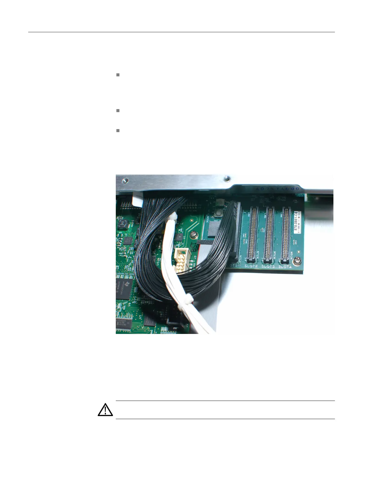
Connecting channel module cables: Install a cable from the Slot 1 connector
on the Main board to the channel 1 module (above the Main board). Route the
channel 1 cable below the white power cable. Repeat for any other Channel
modules: Slot 2 cable connects to the Channel 2 module (top), and so on.(See
Figure 3
-5 on page 3-11.)
Figure 3-9: Installing channel cable example: Slot 1 on the Main board to the
channel 1 module
The channel c ables are directional, with the connector key positioned toward
the front of the instrument on the Main board connectors, and to the right
where it plugs into the channel modules. The key is near pin 60 on the cable,
so be sure to align the cable correctly on both ends.
CAUTION. The channel modules will be damaged when power is applied if the
cables are installed backwards in the connector.
3–14 ECO8000 Series Service Manual

 Loading...
