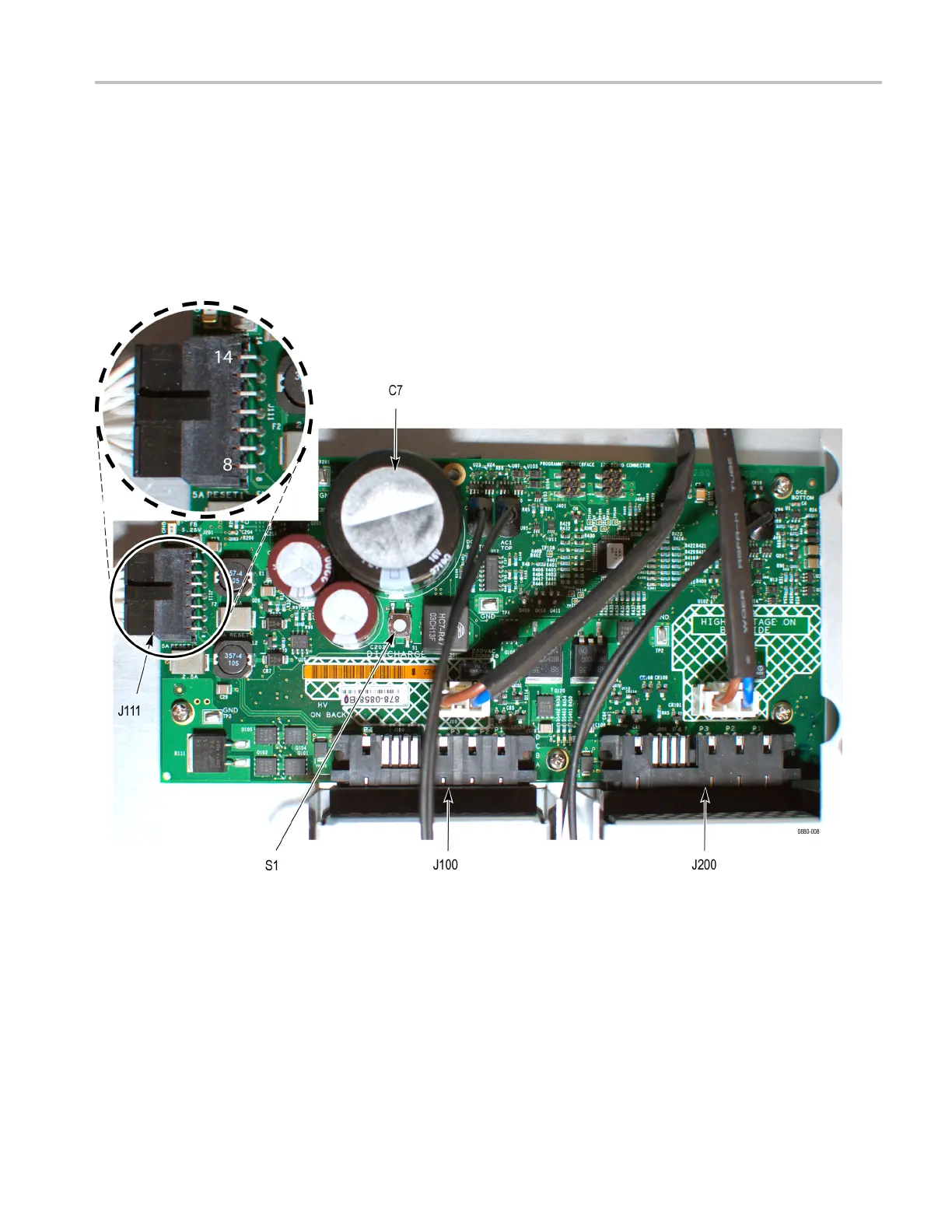
EasyManuals Logo

Tektronix ECO8000 Series Service Manual

Tektronix ECO8000 Series
106 pages
To Next Page IconTo Next Page
To Previous Page IconTo Previous Page
Page #85 background imageLoading...
Page #85 background image
Troubleshooting
5. Measure the 5.2
V output on J111 pin 10. This connector has pins 8-14 on the
outside row, so pin 10 is the third from the bottom (when facing the front of
the instrument. If the 5.2 V is bad, replace the Combiner board.
6. Check the 3.3 V supply on J111 pin 8. This is actually the I2C SDA line,
but should be pulled up to 3.3 V. If not, then check the 3.3 V supply on the
Main board. (See page 4-18, Check the Main board 3.3 V supply and that the
PLD is programmed.)
Figure 4-1: Component locations on the Combiner board
ECO8000 Series Service Manual 4–17

Table of Contents

Other manuals for Tektronix ECO8000 Series

Questions and Answers:

Question and Answer IconNeed help?

Do you have a question about the Tektronix ECO8000 Series and is the answer not in the manual?

Tektronix ECO8000 Series Specifications

General IconGeneral
BrandTektronix
ModelECO8000 Series
CategoryControl Unit
LanguageEnglish

Related product manuals