Theory of operation
This section describes the basic operation of the major circuit blocks or modules
in the ECO8000 Series instruments. The block diagram shows the modules and
functional b
locks in the instrument. (See Figure 2-2.)
Instrument level
The ECO800
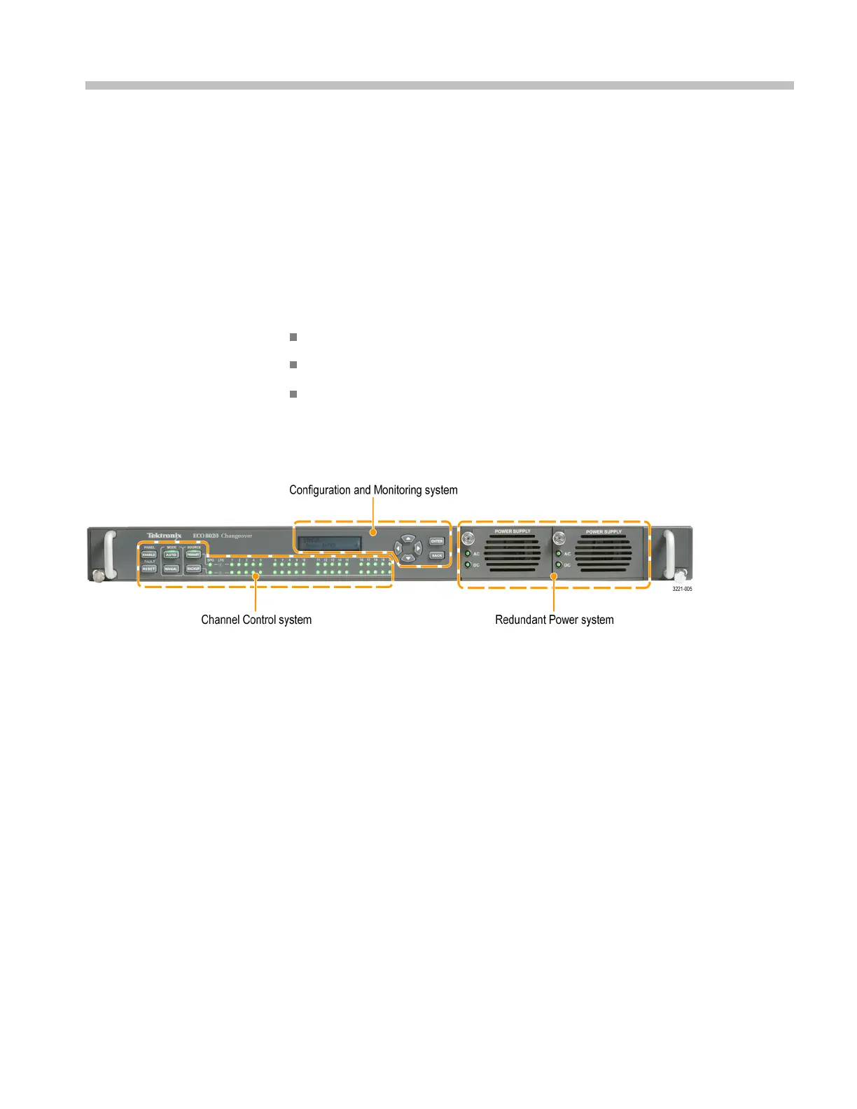
0 and ECO8020 have three major subsystems which are essentially
independent of each other:
Channel C
ontrol system
Configuration and Monitoring system
Redundant Power system
These three subsystems are loosely coupled to achieve maximum reliability of the
main ECO function, which is sensing faults on the input signals and switching to
a backup if necessary.
Figure 2-1: ECO8000 Series subsystems (ECO8020 with Option DPW shown)
Channel Control system
The Channel Control system monitors the signal level on each input, and switches
to the other sync source if a fault occurs. This subsystem is implemented as
as
imple hardware state machine to maximize reliability. This portion of the
instrument is accessed via the left keyboard, and the s tatus is displayed on the
button lights and the per-channel LEDs on the front panel.
When the instrument powers on, the Channel Control system restores all basic
configuration settings that were in place when the instrument was powered off.
This restoration is finished in a fraction of a second and is independent of the
processor booting to run the display and the Configuration and Monitoring system.
If the Configuration and Monitoring system is rebooted, the Channel Control
system is unaffected.
ECO8000 Series Service Manual 2–1

 Loading...
