110
Phaser 740 and 750 Color Printers
Image processor board
Phaser 740
Swap components.
If you are replacing the image processor board, exchange:
■
The Boot ROM (PLCC), requires using a PLCC extraction tool (003-1633-00)
■
The 8-pin NVRAM chip (DIP)
■
The Real Time Clock module
The components contains important customer-created parameters. The printer may
not operate correctly without the components being swapped.
Also transfer from the old board to the new board.
■
The RAM DIMMs
■
The PhaserShare card (if installed)
■
The SCSI card (if installed)
Note
If any DIP switches are mounted on the board, they should be set to
“Open.”
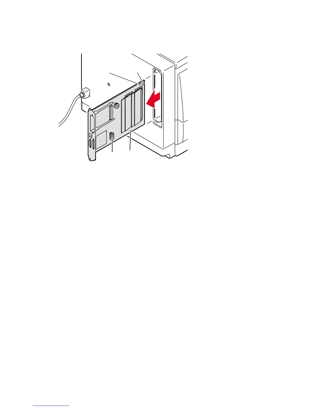
Removing the image processor board
740-7-20
Image
processor
board
Real
Time
clock
Boot
ROM
NV
RAM