Performance Verification
TPS2000 Series Digital Storage Oscilloscopes S ervice Manual
4-9
Press menu button Select settingSelect menu option
ACQUIRE Sample —
MEASURE
Source CH1
Type Pk-Pk
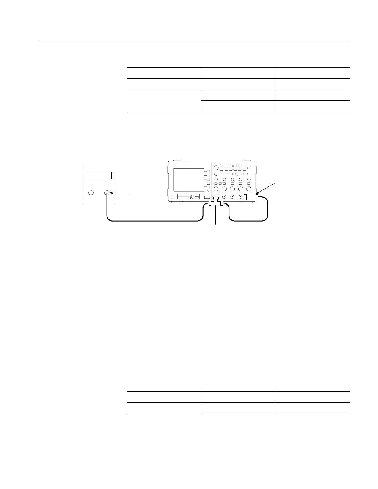
2. Connect the oscilloscope to the leveled sine wave generator as shown below.
Digitizing oscilloscope
Leveled
sine wave
generator
Output
50 Ω
feedthrough
terminator
BNC
cable
BNC cable
BNC T connector
3. Set the leveled sine wave generator frequency to the following:
H 100 MHz if you are checking a TPS2012/2014
H 200 MHz if you are checking TPS2024.
4. Set the oscilloscope VOLTS/DIV to 500 mV/div.
5. Set the oscilloscope SEC/DIV to 10 ns/div.
6. Set the leveled sine wave generator output level to approximately 1 V
p-p
so
that the measured amplitude is approximately 1V. (The measured amplitude
can fluctuate around 1 V.)
7. Press SET LEVEL TO 50%. Adjust TRIGGER LEVEL as necessary and
then check that triggering is stable.
8. Change the oscilloscope setup using the following step:
Press menu button Select menu option Select setting
TRIGGER Slope Falling
 Loading...
