EasyManua.ls Logo

Telefire GUARD-7 - User Manual

Default Icon
93 pages
Print Icon
To Next Page IconTo Next Page
Loading...
Control Panels
ADR-7000 / SAVER-7000 /
GUARD-7
Addressable
Fire Alarm Control Panel
Technical Manual
TELEFIRE FIRE & GAS DETECTORS LTD
PO Box 7036
Petach Tikva 49250
Israel
Tel: 972 3 970 0400
Fax: 972 3 921 1816
eMail: info@telefire.com
Web: www.telefire.com
ADR-7000En 98.pdf
Revision 0.98
October 2017

Table of Contents

Questions and Answers

  • S
    Stephanie HarrisonSep 3, 2025
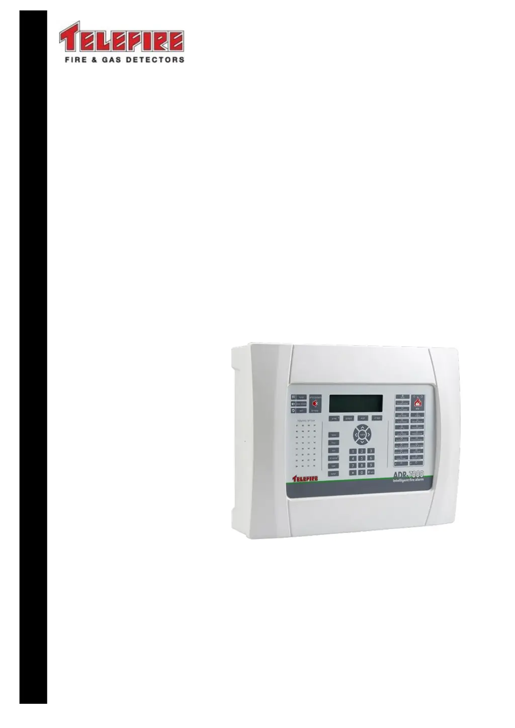
    What causes ' output evacuation circuit is disconnected' on Telefire GUARD-7?
    • J
      Jack BrownSep 3, 2025
      If the Telefire Control Panel displays ' output evacuation circuit is disconnected', it means the output evacuation circuit is disconnected at the extinguishing controller. Reconnect the circuit.
  • K
    Karen SteinSep 2, 2025
    What to do if Telefire GUARD-7 says ' sirens circuit is disconnected'?
    • R
      Rachel HamiltonSep 2, 2025
      If the Telefire Control Panel displays an ' sirens circuit is disconnected' message, it indicates that the siren circuit is disconnected at the extinguishing controller. Reconnect the circuit.
  • M
    Melissa HarrisonAug 31, 2025
    What does 'Panel # communication error' mean on Telefire Control Panel?
    • L
      lawsonjohnAug 31, 2025
      If the Telefire Control Panel displays 'Panel # communication error,' it means a control panel defined as a Partner is disconnected or powered off. Ensure that the control panel is on and verify the connection.
  • C
    christine45Aug 29, 2025
    Why does my Telefire GUARD-7 show 'Main circuit limited current'?
    • B
      brandon27Aug 29, 2025
      If the Telefire Control Panel displays 'Main circuit limited current' for a device, it means that the current has been limited on the designated device. Locate the source of the fault, such as damaged wire or a water leak, and repair it.
  • P
    Paula BentonAug 28, 2025
    What causes 'Main circuit low voltage' on Telefire GUARD-7?
    • C
      Christopher TaylorAug 28, 2025
      If the Telefire Control Panel displays 'Main circuit low voltage' for a specific device, it means the voltage is low on that device. If the device is the battery or backup battery (3V), replace the battery or backup battery (R2032C). Otherwise, the control panel may be faulty and should be sent to the manufacturer for repairs.
  • K
    Karen MitchellAug 27, 2025
    How to fix 'Main circuit short' on a Telefire GUARD-7?
    • C
      Crystal BaileyAug 27, 2025
      If the Telefire Control Panel displays 'Main circuit short' for a device, it indicates a short circuit on that device. Find the cause of the short circuit and remove it.
  • D
    Donna BlackburnAug 25, 2025
    What does 'Main circuit disconnect' mean on my Telefire Control Panel?
    • M
      Mary ScottAug 25, 2025
      If the Telefire Control Panel shows 'Main circuit disconnect' for a specific device, it means that the designated device is disconnected. Check the line continuity and connect an end of line resistor (5.1K?) at the output circuit connectors.
  • B
    brownscottAug 23, 2025
    How to enable a disabled device on Telefire GUARD-7?
    • M
      Melissa ReyesAug 23, 2025
      If your Telefire Control Panel shows 'Disabled,' it indicates that a device or area has been disabled. To enable it: - Open the start/stop device menu from the main menu. - Select the device or area indicated in the message. - Click 'Enable'.

Summary

ADR-7000 Control Panels

Main Board - ADR-7021

Details the primary control board of the ADR-7000 system.

Access Levels

Explains user access control and different security levels.

Work States - Alarm, Fault, Supervisory, Disablement, and Test Modes

Alarm State

Details system behavior during an alarm event.

Fault State

Explains system behavior when a fault occurs.

Test State

Details the mode for system testing without activating outputs.

Installation

Pre-Installation Planning

Planning of quantity and location of devices and system layout.

Installation of Detectors, I;O Modules, and Other Modules

Steps for installing various system devices and modules.

Automatic Extinguishing

Extinguishing Output and Extinguishing Controller

Configures outputs for automatic extinguishing systems.

Manual Activation

Procedures for manually activating extinguishing systems.

Extinguishing Disconnect

Details the function and installation of extinguishing disconnect switches.

System Configuration (Programming) Process

Entering Configuration State

Steps to access the system configuration mode.

System Configuration (Programming)

Walk Test

Procedure for testing all initiating devices in the system.

Troubleshooting

Control Panel Error Messages

Lists and explains error messages displayed by the control panel.

System Faults

Identifies common system faults and their causes/repairs.

Addressable Device Faults

Troubleshooting specific faults related to addressable devices.

Programming Faults

Lists and explains faults encountered during system programming.

Periodic Tests

Warnings and Limitations

General Warnings and Limitations

General warnings about system assembly, configuration, and installation.

Compatibility

Specification

Power Supply

Details the system's power supply capabilities and battery requirements.

Certification

Appendix A - Current Consumption and Battery Capacity Calculation

Table 5 Power Requirement - Final Calculation

Final calculation of battery requirement and system load.

When are Auxiliary Power Supplies Needed?

Appendix B - Detector Sensitivity Selection

Appendix C - Standards Compliance

UL 864 Compliance

Confirms UL 864 compliance for the ADR-7000 system.

EN 12094-1 Compliance

Outlines compliance with EN 12094-1 for extinguishing systems.

Telefire GUARD-7 Specifications

General IconGeneral
Zones7
Input Voltage230VAC
Operating Temperature-10°C to +55°C
Enclosure ProtectionIP30
Sounder circuits1
Battery12V/7Ah
Weight2.5 kg
CompatibilityConventional detectors

Related product manuals