17
Introduction
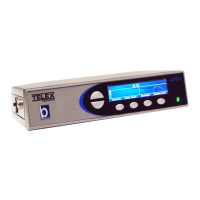
Back Plane Connections
1. USB Port - The USB Port is used to connect the ADHB-4 to a computer.
2. 10/100 NETWORK Port - The 10/100 NETWORK port is used to connect the ADHB-4 to an IP Network with a
standard RJ-45 Ethernet interface cable. The Ethernet port connector supports a Base 10/100 Cat 5E connection.
3. NENA Jack - The NENA (National Emergency Number Association) jack is used to connect an RJ-12 NENA
phone.
4. PHONE Jack - The PHONE Jack is used to connect a phone handset supplied with a mini RJ 4-pin connector.
5. FOOTSWITCH Jack - The FOOTSWITCH jack is used to connect a footswitch and supports two inputs: PTT and
monitor.
6. ACCESSORY Port - The ACCESSORY port supports a DB-15 to provide access to miscellaneous functionality.
7. REMOTE HEADSET Ports (1 and 2) - The REMOTE HEADSET ports (1 and 2) are used to connect an optional
RHB (Remote Headset Box) using the DB-9 cable supplied with the RHB unit. Up to two (2) RHBs can be
connected.
8. DESKMIC Jack (RJ11) - The DESKMIC jack is used to connect an RJ-11–fitted electret or dynamic microphone.
9. SPEAKER 1–2, 3–4, 5–6 Jacks - Each SPEAKER jack is used to connect a speaker pair. These three (3) receptacles
are equipped with 3.5mm stereo jacks requiring self-powered, amplified PC type speakers.
10. POWER Jack - The POWER jack is used to connect a 2.5mm center positive plug supplied by 12 to 16VDC power.
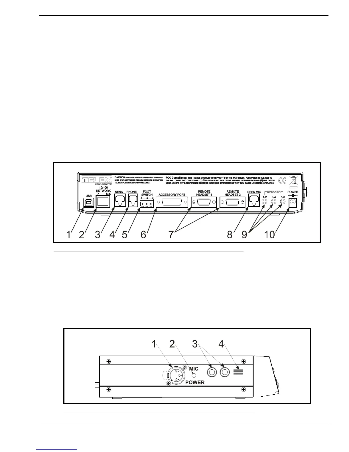
Side Panel Connections
1. MIC (XLR) Connector - The MIC connector is used to connect a 3-pin XLR dynamic microphone. PTT is initiated
from C-Soft or a footswitch.
2. POWER LED Indicator - The LED indicates phantom power is supplied to the XLR jack when lit.
3. HEADSET Jack - The HEADSET jack is used to connect a headset with dual channel 1/4” plugs.
4. Polarity Hash Marks.- Polarity Hash Marks are provided on the side of the unit to indicate headset connector
orientation.
FIGURE 2. ADHB-4 Back Plane Connections
FIGURE 3. ADHB-4 Side Panel Connections