25
Installation
REMOTE HEADSET (1 and 2) Connectors
The REMOTE HEADSET (1 and 2) connectors are used to connect RHB’s. The RHB ships with a
DB-9 (male) to DB-9 (female) cable. Pin outs are shown in Table 2 on page 25.
NOTE: For more information, see “Remote Headset Box” on page 73.
DESK MIC Jack
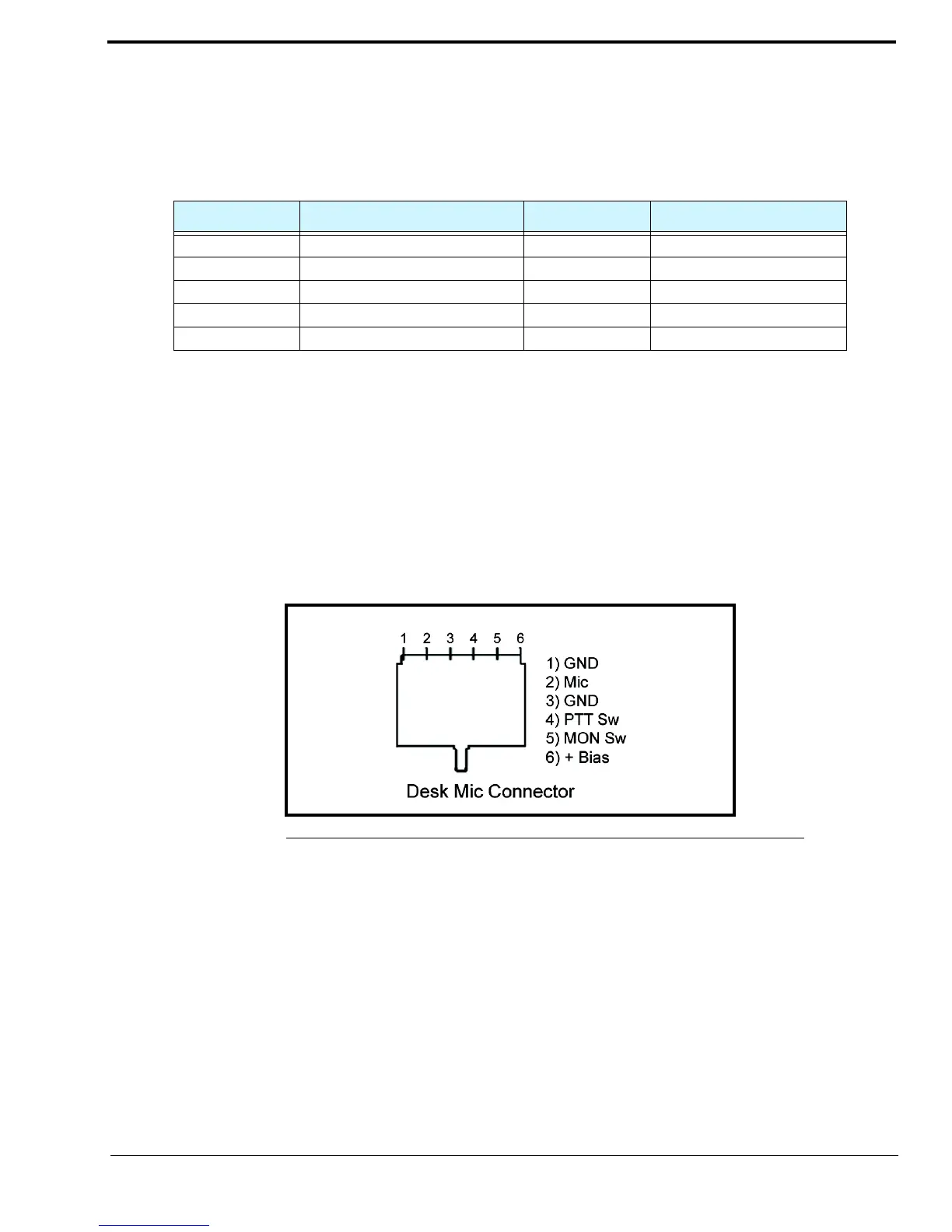
The DESK MIC jack is used to connect an electret or dynamic desk mic with an RJ-11 connector, to the ADHB-4. The RJ-11
modular jack is designed specifically for Bosch microphone models: MD2000 (electret element) or model 6513 (dynamic
element); however, any microphone conforming to the input amplifier specifications may be wired for use.
If an electret microphone is used, a DC bias is placed on the microphone connection to power the microphone.
The nominal audio input levels are 500mv P-P for an electret and or 10-20mv P-P for a dynamic element.
RJ11 Connector
MIC (XLR) Connector
The MIC (XLR) connector, on the side panel, is used to connect a 3-pin XLR-fitted microphone to the ADHB-4. The XLR
microphone input stage is designed for any standard balanced low impedance dynamic microphone.
A phantom power supply of +48VDC is available for microphones that require power. The +DC is equally applied to pins 2
and 3 of the connector with reference to pin 1 (ground). Phantom power to the XLR jack is set in the configuration windows.
This type of connector does not provide PTT. PTT must be initiated from either C-Soft or a footswitch.
The nominal input level is 10-20mv P-P.
TABLE 2. DB-9 Pin Outs
Pin Number Signal Pin Number Signal
1 Headset Ear GND/Unselect 6 Headset PTT
2 GND 7 +12VDC
3 GND 8 LED Control
4 Headset Ear 9 Open
5 Headset Microphone
FIGURE 9. RJ-11 Pin Outs—Desk Mic Jack