EasyManuals Logo

Telit Wireless Solutions ME910G1 Design Guide

Telit Wireless Solutions ME910G1
93 pages
To Next Page IconTo Next Page
To Previous Page IconTo Previous Page
Page #49 background imageLoading...
Page #49 background image
ME910G1 Hardware Design Guide
1VV0301593 Rev.12 Page 49 of 93 2021-09-24
Not Subject to NDA
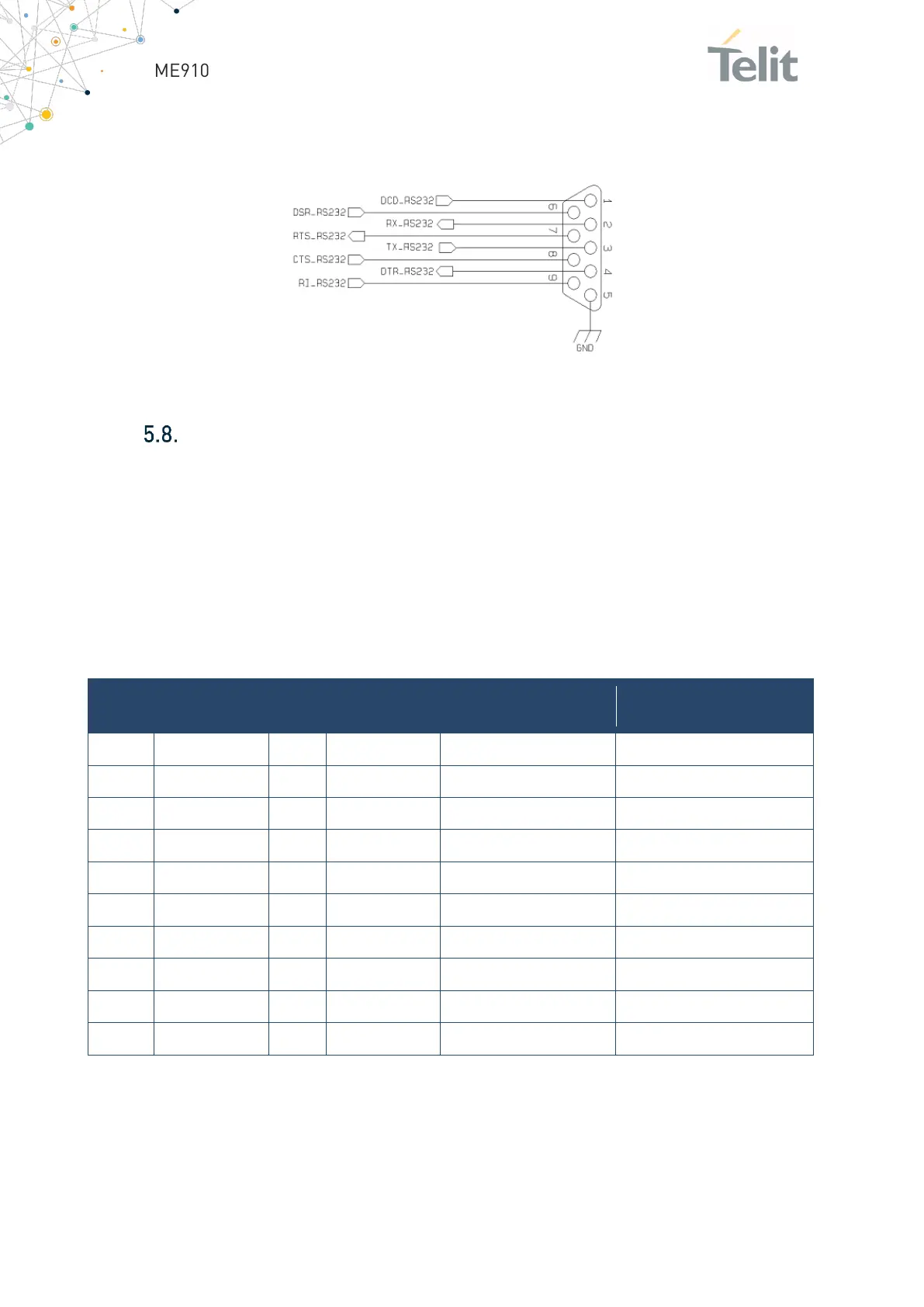
The RS232 serial port lines are usually connected to a DB9 connector with the following
layout:
Figure 15: example RS232 serial port lines
General Purpose I/O
The ME910G1 module includes a set of Configurable Digital Input / Output pins (CMOS
1.8V). The Input pads can only be read; they report the digital value (high or low) present
on the pad at the time of reading. The Output pads can only be written or queried and set
the value of the pad output.
An alternate function pad is controlled internally by the ME910G1 firmware and acts
depending on the function implemented.
The following table shows the available GPIO on the ME910G1:
PAD
Signal
I/O
Output Drive
Strength
Default State
NOTE
C8
GPIO_01
I/O
1mA
INPUT PD (100K)
Alternate function STAT LED
C9
GPIO_02
I/O
1mA
INPUT PD (100K)
C10
GPIO_03
I/O
1mA
INPUT PD (100K)
C11
GPIO_04
I/O
1mA
INPUT PD (100K)
B14
GPIO_05
I/O
1mA
INPUT PD (100K)
C12
GPIO_06
I/O
1mA
INPUT PD (100K)
C13
GPIO_07
I/O
1mA
INPUT PD (100K)
K15
GPIO_08
I/O
1mA
INPUT PD (100K)
L15
GPIO_09
I/O
1mA
INPUT PD (100K)
G15
GPIO_10
I/O
1mA
INPUT PD (100K)
Table 24: ME910G1 available GPIO

Table of Contents

Other manuals for Telit Wireless Solutions ME910G1

Questions and Answers:

Question and Answer IconNeed help?

Do you have a question about the Telit Wireless Solutions ME910G1 and is the answer not in the manual?

Telit Wireless Solutions ME910G1 Specifications

General IconGeneral
BrandTelit Wireless Solutions
ModelME910G1
CategoryWireless modules
LanguageEnglish

Related product manuals