ME910G1 Hardware Design Guide
1VV0301593 Rev.12 Page 50 of 93 2021-09-24
Using a GPIO as INPUT
GPIO pads, when used as inputs, can be connected to the digital output of another device
to report its status, provided this device has interface levels compatible with the 1.8V
CMOS levels of the GPIO.
If the digital output of the device to be connected with the GPIO input pad of ME910G1 has
interface levels other than the 1.8V CMOS, then it can be buffered with an open collector
transistor with a 47K pull up to 1.8V supplied by VAUX/POWERMON R11 pad.
Note: To avoid a back powering, it is recommended to prevent any
HIGH logic level signal from being applied to the digital pins of the
ME910G1 when the module is powered off or during an ON/OFF
transition. Refer to ME910G1 series AT command reference guide for
GPIO pins configuration.
Using a GPIO as OUTPUT
GPIO pads, when used as outputs, can drive 1.8V CMOS digital devices or compatible
hardware. When set as outputs, the pads have a push-pull output and therefore the pull-
up resistor may be omitted.
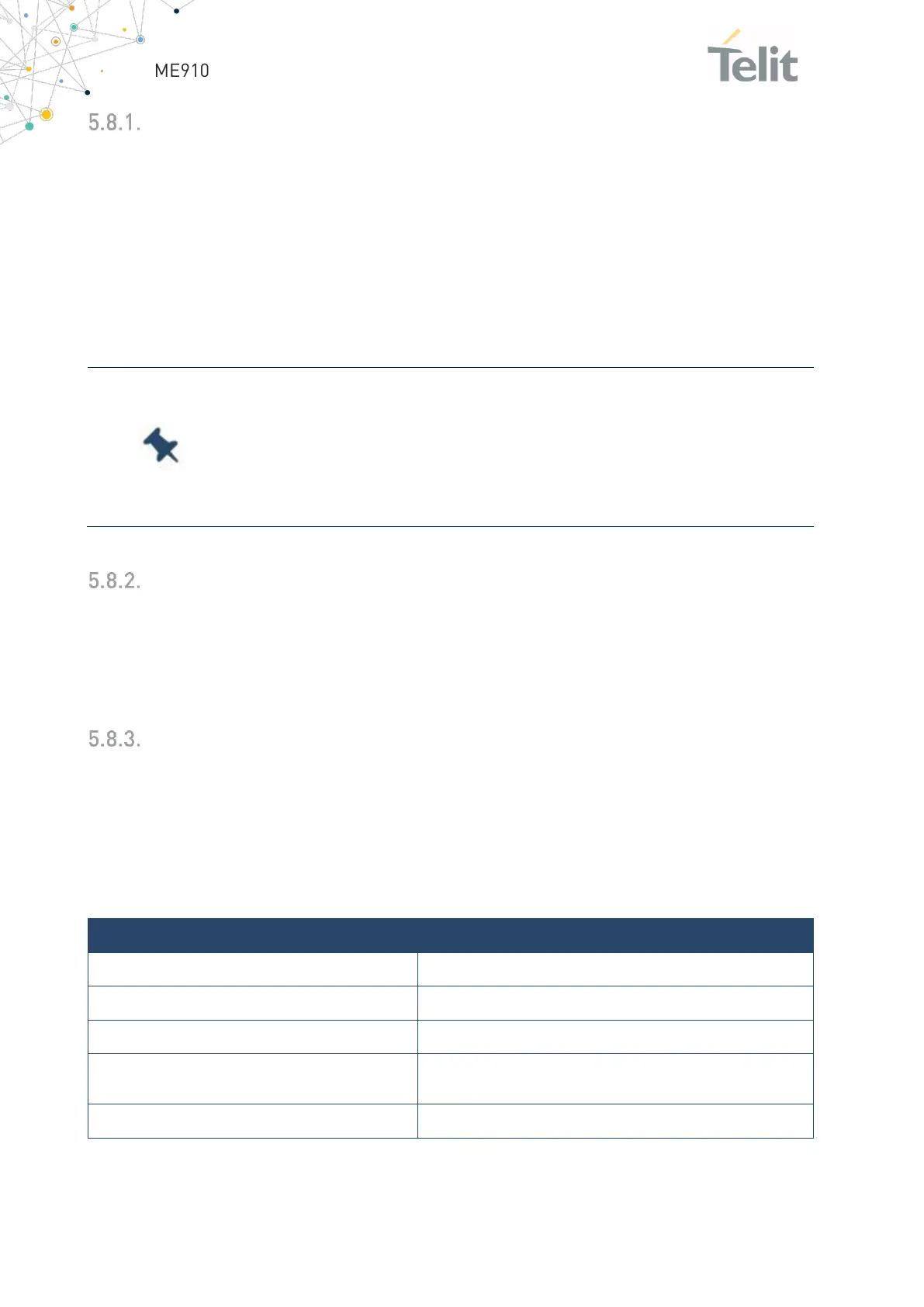
Indication of Network Service Availability
The STAT_LED pin status shows information on the network service availability and Call
status. The function is available as an alternate function of GPIO_01 (to be enabled using
the AT#GPIO=1,0,2 command). In the ME910G1 modules, the STAT_LED needs an
external transistor to drive an external
LED and its voltage level is defined according to the table below:
Blinking 1sec on + 2 sec off
Registered in idle + power saving
It depends on the event that triggers the wakeup (In sync
with network paging)
Blinking 1 sec on + 2 sec off
Table 25: LED and its status

 Loading...


